- •Contents
- •List of Figures
- •List of Tables
- •About the Author
- •Acknowledgements
- •Abbreviations
- •Introduction
- •1 Hardware Design
- •1.1 Separation of Routing and Forwarding Functionality
- •1.2 Building Blocks
- •1.2.1 Control Module
- •1.2.2 Forwarding Module
- •1.2.4 Stateful Failover
- •1.3 To Flow or Not to Flow?
- •1.4 Hardware Redundancy, Single Chassis or Multi Chassis
- •2 Transport Media
- •2.1 Maximum Transmission Unit (MTU)
- •2.1.1 Path MTU Discovery
- •2.1.2 Port Density
- •2.1.3 Channelized Interfaces
- •2.2 Ethernet
- •2.2.1 Address Resolution Protocol (ARP)
- •2.3 Asynchronous Transfer Mode (ATM)
- •2.4 Packet Over SONET (POS)
- •2.5.1 Intelligent Protection Switching
- •2.6 (Fractional) E1/T1/E3/T3
- •2.7 Wireless Transport
- •2.7.1 Regulatory Constraints
- •2.7.2 Interference
- •2.7.3 Obstructions
- •2.7.4 Atmospheric Conditions
- •3.1.1 Management Ethernet
- •3.1.2 Console Port
- •3.1.3 Auxiliary (Aux) Port
- •3.1.4 Remote Power Management
- •3.1.5 Uninterruptible Power Supplies (UPS)
- •3.2 Network Time Protocol (NTP)
- •3.3 Logging
- •3.4 Simple Network Management Protocol (SNMP)
- •3.4.1 SNMPv1, v2c and v3
- •3.5 Remote Monitoring (RMON)
- •3.6 Network Management Systems
- •3.6.1 CiscoWorks
- •3.6.2 JUNOScope
- •3.7.1 Concurrent Version System (CVS)
- •3.8 To Upgrade or Not to Upgrade
- •3.8.1 Software Release Cycles
- •3.9 Capacity Planning Techniques
- •4 Network Security
- •4.1 Securing Access to Your Network Devices
- •4.1.1 Physical Security
- •4.1.2 Authentication, Authorization and Accounting (AAA)
- •4.2 Securing Access to the Network Infrastructure
- •4.2.1 Authentication of Users, Hosts and Servers
- •4.2.2 Encryption of Information
- •4.2.3 Access Tools and Protocols
- •4.2.4 IP Security (IPsec)
- •4.2.5 Access Control Lists
- •4.2.6 RFC 1918 Addresses
- •4.2.7 Preventing and Tracing Denial of Service (DoS) Attacks
- •5 Routing Protocols
- •5.1 Why Different Routing Protocols?
- •5.2 Interior Gateway Protocols (IGP)
- •5.2.1 Open Shortest Path First (OSPF)
- •5.2.2 Authentication of OSPF
- •5.2.3 Stub Areas, Not So Stubby Areas (NSSA) and Totally Stubby Areas
- •5.2.4 OSPF Graceful Restart
- •5.2.5 OSPFv3
- •5.2.8 IS-IS Graceful Restart
- •5.2.9 Routing Information Protocol (RIP)
- •5.2.10 Interior Gateway Routing Protocol (IGRP) and Enhanced Interior Gateway Routing Protocol (EIGRP)
- •5.2.11 Diffusing Update Algorithm (DUAL)
- •5.2.12 Stuck-in-Active
- •5.2.13 Why use EIGRP?
- •5.3 Exterior Protocols
- •5.3.1 Border Gateway Protocol (BGP)
- •5.3.2 Authentication of BGP
- •5.3.3 BGP Graceful Restart
- •5.3.4 Multiprotocol BGP
- •6 Routing Policy
- •6.1 What is Policy For?
- •6.1.1 Who Pays Whom?
- •6.2 Implementing Scalable Routing Policies
- •6.3 How is Policy Evaluated?
- •6.3.2 The Flow of Policy Evaluation
- •6.4 Policy Matches
- •6.5 Policy Actions
- •6.5.1 The Default Action
- •6.5.2 Accept/Permit, Reject/Deny, and Discard
- •6.6 Policy Elements
- •6.7 AS Paths
- •6.9 Internet Routing Registries
- •6.10 Communities
- •6.11 Multi-Exit Discriminator (MED)
- •6.12 Local Preference
- •6.13 Damping
- •6.14 Unicast Reverse Path Forwarding
- •6.15 Policy Routing/Filter-Based Forwarding
- •6.16 Policy Recommendations
- •6.16.1 Policy Recommendations for Customer Connections
- •6.16.2 Policy Recommendations for Peering Connections
- •6.16.3 Policy Recommendations for Transit Connections
- •6.17 Side Effects of Policy
- •7 Multiprotocol Label Switching (MPLS)
- •7.2 Label Distribution Protocols
- •7.3 Tag Distribution Protocol (TDP)
- •7.4 Label Distribution Protocol (LDP)
- •7.4.1 LDP Graceful Restart
- •7.5.1 RSVP-TE Graceful Restart
- •7.6 Fast Reroute
- •7.7 Integrating ATM and IP Networks
- •7.8 Generalized MPLS (GMPLS)
- •8 Virtual Private Networks (VPNs)
- •8.1 VPNs at Layer 3
- •8.1.1 Layer 3 VPN (RFC 2547bis)
- •8.1.2 Generic Router Encapsulation (GRE)
- •8.1.3 IPsec
- •8.2 VPNs at Layer 2
- •8.2.1 Circuit Cross-Connect (CCC)
- •8.2.3 Martini (Layer 2 circuits)
- •8.2.4 Virtual Private Wire Service (VPWS)
- •8.2.5 Virtual Private LAN Service (VPLS)
- •8.2.6 Layer 2 Tunnelling Protocol (L2TP)
- •9.1 Design and Architectural Issues of CoS/QoS
- •9.2 CoS/QoS Functional Elements
- •9.2.3 Congestion Avoidance Mechanisms
- •9.2.4 Queueing Strategies
- •9.3 QoS Marking Mechanisms
- •9.3.1 Layer 2 Marking
- •9.3.2 Layer 3 QoS
- •9.3.3 MPLS EXP
- •9.4 Integrating QoS at Layer 2, in IP and in MPLS
- •9.4.1 DiffServ Integration with MPLS
- •10 Multicast
- •10.1 Multicast Forwarding at Layer 2
- •10.1.1 Multicast on Ethernet and FDDI
- •10.1.2 Multicast Over Token Ring
- •10.1.3 Internet Group Management Protocol (IGMP)
- •10.1.4 IGMP Snooping
- •10.1.5 PIM/DVMRP Snooping
- •10.1.6 Immediate Leave Processing
- •10.1.7 Cisco Group Management Protocol (CGMP)
- •10.2 Multicast Routing
- •10.2.1 Reverse Path Forwarding (RPF) Check
- •10.2.2 Dense Mode Protocols
- •10.2.3 Sparse Mode Protocols
- •10.2.4 Multicast Source Discovery Protocol (MSDP)
- •10.2.5 Multiprotocol BGP
- •10.2.6 Multicast Scoping
- •11.1 Evolution and Revolution
- •11.2 IPv6 Headers
- •11.3 IPv6 Addressing
- •11.3.1 Hierarchical Allocations
- •11.3.2 Address Classes
- •11.5 Domain Name System (DNS)
- •11.6 Transition Mechanisms
- •11.6.1 Dual Stack
- •11.6.3 Tunnelling IPv6 in IPv4
- •11.7 Routing in IPv6
- •11.7.2 OSPFv3
- •11.7.3 RIPng
- •11.7.4 Multiprotocol BGP
- •11.8 Multicast in IPv6
- •11.9 IPv6 Security
- •11.10 Mobility in IPv6
- •References
- •Index
2.5 SRP/RPR AND DPT |
15 |
2.5.1INTELLIGENT PROTECTION SWITCHING
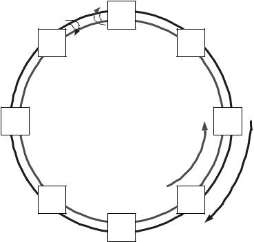
One of the features of SRP is the ability to protect against single or double fibre breaks or the total loss of a router. For two such examples, see Figures 2.3 and 2.4. In Figure 2.3 the link between R1 and R8 is broken in both directions (although, in most senses, the same processes would apply if only one of the fibres was broken). As R1 and R8 notice that they are no longer receiving traffic, each will internally wrap the failed transmit circuit back onto the receive circuit. This will create a new topology, and all nodes will be informed that there is a ring wrap. IPS failure protection and restoration are achieved in less than 50 milliseconds, which is equivalent to the restoration speeds required by SONET and SDH systems.
In Figure 2.4, router R1 has failed. In this case, R2 and R8 will identify the failure. Each will then wrap the transmit port normally transmitting towards R1 back to the receive port from R1. Again, the topology will change and all nodes will be informed of the fact that there is a ring wrap on the network.
A well-designed DPT or RPR network can provide exceptionally efficient connectivity over local and wide area networks. In theory, it is possible to build DPT/RPR rings spanning entire continents and including up to 255 nodes. However, this is unlikely to be the most efficient use of this media. Constraining the diameter and, more importantly,
|
X |
R1 |
|
R8 |
R2 |
||
|
R7 |
R3 |
R6 |
R4 |
|
R5 |
Figure 2.3 Both fibres cut at a single point, ring wrapped at adjacent nodes
16 |
TRANSPORT MEDIA |
|
R1 |
|
X |
R8 |
R2 |
R7 |
R3 |
R6 |
R4 |
|
R5 |
Figure 2.4 Node lost, ring wrapped at adjacent nodes
the number of nodes on the ring will improve the efficiency of the network. In reality, no more than 64 nodes are permitted on a single ring.
2.6 (FRACTIONAL) E1/T1/E3/T3
These lower speed interfaces are commonly used between the provider edge and customer edge. Despite the significant inroads being made by Ethernet to the edge, these interfaces are still dominant because of the lack of widespread availability of Ethernet-based services beyond the urban centres.
The major problem associated with these interfaces is their large number. Traditionally, these are the interfaces over which all customers have been connected to their service providers’ networks. When each customer is presented over a single X.21, RJ48, or coax pair, there is a limit to the number of customers who can be serviced in a specific amount of router real estate. In order to overcome this constraint, it is now common for telcos to aggregate many of these circuits over a single SONET or SDH presentation (e.g. 61 E1s presented over a single STM-1, 12 DS-3s presented over a single OC12). This ‘channelization’ is actually fundamental to the way SONET and SDH work so it requires no additional functionality within those protocols. The only extensions required are to the service offerings of the telcos and to the interfaces on routers.