
IPv6 Essentials
.pdf
138 |
Router Renumbering |
|
RFC 2894 |
|
|
|
|
|
|||
ICMP |
Node |
Information |
|
|
|
|
|
||||
139 |
|
|
|
|
|
|
|
||||
Query |
|
|
|
Draft |
number |
at |
the |
time |
of |
writing: |
|
|
|
|
|
|
http://www.ietf.org/internet-drafts/draft-ietf-ipngwg-icmp- |
||||||
140 |
ICMP |
Node |
Information |
name-lookups-09.txt. |
|
|
|
|
|
||
|
Response |
|
|
|
|
|
|
|
|
|
|
141 |
Inverse ND Solicitation |
RFC 3122 |
|
|
|
|
|
||||
142 |
Inverse ND Adv Message |
RFC 3122 |
|
|
|
|
|
||||
|
ICMP |
Home Agent |
Address |
|
|
|
|
|
|
|
|
|
Discovery Request Message |
|
|
|
|
|
|
|
|||
150 |
ICMP |
Home Agent |
Address |
Experimental / Draft—ICMPv6 Messages for Mobile IPv6 |
|||||||
|
|||||||||||
151 |
Discovery Reply Message |
Draft number at time of writing: http://www.ietf.org/internet- |
|||||||||
|
|
|
|
||||||||
|
|
|
|
|
|||||||
152 |
ICMP |
Mobile |
|
Prefix |
drafts/draft-ietf-mobileip-ipv6-18.txt. |
|
|
|
|||
Solicitation Message Format |
|
|
|
|
|
|
|
||||
|
Message numbers have not yet been assigned by IANA. |
||||||||||
153 |
ICMP |
Mobile |
|
Prefix |
|||||||
|
|
|
|
|
|
|
|
||||
|
|
|
|
|
|
|
|
|
|||
|
Advertisement |
|
Message |
|
|
|
|
|
|
|
|
|
Format |
|
|
|
|
|
|
|
|
|
|
4.2 ICMP Error Messages
Every ICMP message can have a slightly different header depending on the kind of error report or information it carries. The following sections outline the structure of each type of ICMPv6 message.
4.2.1 Destination Unreachable
A Destination Unreachable message is generated if an IP datagram cannot be delivered. A Type field with the value 1 identifies this message. The ICMP message is sent to the source address of the invoking packet. The format of the Destination Unreachable message is shown in Figure 4-2.
Figure 4-2. Format of the Destination Unreachable message
The Type field is set to one, which is the value for the Destination Unreachable message. The Code field supplies more information about the reason why the datagram was not delivered. The possible codes are listed in Table 4-3. The data portion of the ICMP message contains parts of the original message—as much as will fit into the ICMP message.
41

Table 4-3. Code values of the Destination Unreachable message (type 1)
Code
 Description
No route to destination
0This message is generated if a router cannot forward a packet because it does not have a route in its table for a destination network. This can only happen if the router does not have an entry for a default route.
Communication with destination administratively prohibited
1This type of message can, for example, be sent by a firewall that cannot forward a packet to a host inside the firewall because of a packet filter. It might also be sent if a node is configured not to accept unauthenticated Echo Requests.
Beyond scope of source address
2This code is used when the multicast scope of the source address is smaller than the scope of the destination address. This code is a draft at the time of writing (http://www.ietf.org/internet- drafts/draft-ietf-ipngwg-icmp-v3-02.txt).
Address unreachable
3
This code is used if a destination address cannot be resolved into a corresponding network address or if there is a data-link layer problem preventing the node from reaching the destination network.
Port unreachable
4This code is used if the transport protocol (e.g., UDP) has no listener and if there is no other means to inform the sender. For example, if a Domain Name System (DNS) query is sent to a host and the DNS server is not running, this type of message is generated.
If the destination is unreachable due to congestion, no ICMP message is generated. A host that receives a Destination Unreachable message must inform the upper-layer process.
4.2.2 Packet Too Big
If a router cannot forward a packet because it is larger than the MTU of the outgoing link, it will generate a Packet Too Big message (shown in Figure 4-3). This ICMPv6 message type is used as part of the Path MTU discovery process discussed later in this chapter. The ICMP message is sent to the source address of the invoking packet.
Figure 4-3. Format of the Packet Too Big message
The Type field has the value 2, which identifies the Packet Too Big message. In this case, the Code field is not used and is set to zero. The important information for this type of message is the MTU field, which contains the MTU size of the next hop link.
42
RFC 2463 states that an ICMPv6 message should not be generated as a response to a packet with an IPv6 multicast destination address, a link-layer multicast address, or a link-layer broadcast address. The Packet Too Big message is an exception to this rule. Because the ICMP message contains the supported MTU of the next hop link, the source host can determine the MTU that it should use for further communication. A host that receives a Packet Too Big message must inform the upper-layer process.
4.2.3 Time Exceeded
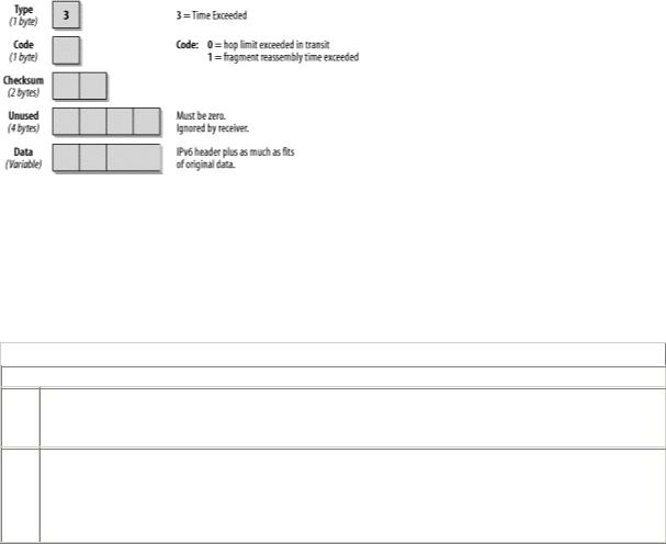
When a router forwards a packet, it always decrements the hop limit by one. Remember, the hop limit makes sure that a packet does not endlessly travel through a network. If a router receives a packet with a hop limit of one and decrements the limit to zero, it discards the packet, generates a Time Exceeded message with a code value of zero, and sends this message back to the source host. This error can indicate a routing loop or the fact that the sender's initial hop limit is too low. It can also tell you that someone used the traceroute utility, which is described later in the chapter. Figure 4-4 shows the format of the Time Exceeded message.
Figure 4-4. Format of the Time Exceeded message
The Type field carries the value 3, specifying the Time Exceeded message. The Code field can be set to 0, which means hop limit exceeded in transit, or to 1, which means that the fragment reassembly time is exceeded. The data portion of the ICMP message contains parts of the original message—as much as fits into the ICMP message, depending on the MTU used.
An incoming Time Exceeded message must be passed to the upper-layer process. Table 4-4 shows the Code fields for the Time Exceeded message.
Table 4-4. Code values for Time Exceeded message (type 3)
Code
 Description
Hop limit exceeded in transit.
0
Possible causes: the initial hop limit value is too low, or there are routing loops.
Fragment reassembly time exceeded.
1If a fragmented packet is sent by using a fragment header (refer to Chapter 2 for more details) and the receiving host cannot reassemble all packets within a certain time, it notifies the sender by issuing this ICMP message.
The hop limit exceeded in transit message type is commonly used to do the traceroute function. Traceroute is helpful in determining the path that a packet takes when traveling through the network. In order to do this, a first packet is sent out with a hop limit of one. The first router in the path decrements the hop limit to zero, discards the packet, and sends back an ICMP message type three, code zero. The source host now knows the address of the first hop router. Next, it sends out a second packet with a hop limit of two. This packet is forwarded by the first router, which decrements the hop limit to one. The second router
43
in the path decrements the hop limit to zero, discards the packet, and sends back an ICMP message type three, code zero. Now the source knows about the second router in the path. Raising the hop limit by one (with every packet sent until the packet reaches the final destination) continues this process. Every router in the path to the final destination sends an ICMP message back to the source host, thereby providing its IP address. It is important to know that if there are redundant paths to the destination, traceroute does not necessarily show the same route for all tests because it might choose different paths.
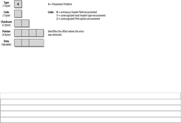
4.2.4 Parameter Problem
If an IPv6 node cannot complete the processing of a packet because it has a problem identifying a field in the IPv6 header or in an Extension header, it must discard the packet and it should send an ICMP Parameter Problem message back to the source of the problem packet. This type of message is often used when an error that does not fit into any of the other categories is encountered. The format of this ICMP message is shown in Figure 4-5.
Figure 4-5. Format of the Parameter Problem message
The Type field has the value 4, which specifies the Parameter Problem message. The Code field can contain any of the three values described in Table 4-5. The Pointer field identifies at which byte in the original packet the error was detected. The ICMP message includes as much of the original data as fits up to the minimum IPv6 MTU. It is possible that the pointer points beyond the ICMPv6 message. This would be the case if the field in error was beyond what can fit in the maximum size of an ICMPv6 error message.
Table 4-5 shows the Code fields for the Parameter Problem message.
Table 4-5. Code values for Parameter Problem (type 4)
Code 
 Description
0
 Erroneous header field encountered
1
 Unrecognized next header type encountered
2
 Unrecognized IPv6 option encountered
For example, if you see an ICMPv6 message of type 4 with a code value of 1 and a pointer set to 40, this indicates that the next header type in the header following the IPv6 header was unrecognized.
4.3 ICMP Informational Messages
In RFC 2463, two types of informational messages are defined: the Echo Request and the Echo Reply messages. Other ICMP informational messages are used for Path MTU Discovery and neighbor discovery. These messages are discussed at the end of this chapter and defined in RFC 2461, "Neighbor Discovery for IP Version 6," and RFC 1981, "Path MTU Discovery for IP version 6."
The Echo Request and Echo Reply messages are used for one of the most common TCP/IP utilities: Packet INternet Groper (ping). Ping is used to determine if a specified host is available on the network and ready
44
to communicate. The source host issues an Echo Request message to the specified destination. The destination host, if available, responds with an Echo Reply message. In Chapter 11, you can find a screenshot that shows you what an IPv6 ping looks like in the trace file, as well as the command you need to ping over IPv6.
4.3.1 Echo Request Message
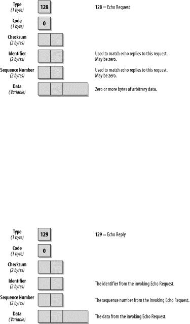
The format of the Echo Request message is shown in Figure 4-6.
Figure 4-6. Format of the Echo Request message
The Type Field is set to 128, the value for the Echo Request. The Code Field is not used for this message and is therefore set to zero. The Identifier and Sequence Number fields are used to match requests with replies. The reply must always contain the same numbers as the request. Whether an identifier and a sequence number are used and what kind of arbitrary data is included in the Echo Request depends on the TCP/IP stack you are using. When you analyze trace files with Echo Request and Echo Reply messages and you are familiar with some stacks, you can determine the TCP/IP stack of the sender by looking at the arbitrary data. You can see an example of this in Figure 4-8, later in this chapter.
4.3.2 Echo Reply
The format of the Echo Reply message is very similar to that of the Echo Request, as shown in Figure 4-7.
Figure 4-7. Format of the Echo Reply message
The Type field contains the value 129 for Echo Reply. The Code field is unused and set to zero. The Identifier and Sequence Number fields must match the fields in the request. The data of the Echo Request message must be copied into the reply entirely and unmodified. If an upper-layer process initiated the Echo Request, the reply must be passed to that process. If the Echo Request message was sent to a unicast
45

address, the source address of the Echo Reply message must be the same as the destination address of the Echo Request message. If the Echo Request was sent to an IPv6 multicast address, the source address of the Echo Reply must be a unicast address of the interface on which the multicast Echo Request was received.
ICMPv6 Echo Request and Reply messages can be authenticated, using an IPv6 authentication header. This means that a node can be configured to ignore nonauthenticated ICMPv6 pings and provide protection against different sorts of ICMPv6 attacks.
4.4 Processing Rules
There are several rules that govern processing of ICMP packets. They can be found in RFC 2463 and are summarized as follows:
•If a node receives an ICMPv6 error message of unknown type, it must pass it to the upper layer.
•If a node receives an ICMPv6 informational message of unknown type, it must be silently discarded.
•As in ICMPv4, as much as possible of the packet that caused the ICMP error message will be included in the ICMP message body. The ICMP packet should not exceed the minimum IPv6 MTU.
•If the error message has to be passed to the upper-layer protocol, the protocol type is determined by extracting it from the original packet (present in the body of the ICMPv6 error message). In case the protocol type cannot be found in the body of the ICMPv6 message (because there were too many extension headers present in the original packet and the part of the header that contained the upper-layer protocol type was truncated), the ICMPv6 message is silently discarded.
An ICMPv6 message must not be sent in the following cases:
•As a result of an ICMPv6 error message.
•As a result of an ICMPv6 redirect message.
•As a result of a packet sent to an IPv6 multicast address. There are two exceptions to this rule: the Packet Too Big message that is used for Path MTU discovery and the Parameter Problem with the code value 2 for an unrecognized IPv6 option.
•As a result of a packet sent as a link-layer multicast (same exceptions as above apply).
•As a result of a packet sent as a link-layer broadcast (same exceptions as above apply).
•As a result of a packet whose source address does not uniquely identify a single node. This could be an IPv6 unspecified address, an IPv6 multicast address, or an IPv6 address known to be an anycast address.
Every IPv6 node must implement a rate-limiting function that limits the rate of ICMPv6 messages it sends. The configurable limit can be either timeror bandwidth-based. If this function is implemented properly, it protects against denial-of-service attacks.
4.5 The ICMPv6 Header in a Trace File
After reading through all that dry information, you deserve something different. The following screenshot (Figure 4-8) shows what a ping looks like in the trace file and provides details of many of the fields we have discussed so far.
46
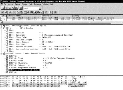
Figure 4-8. Echo Request in a trace file
The two frames in this trace file were captured when my Windows 2000 host issued a ping command to a Linux host. Note that the source address of the second frame, the Echo Reply, is the same as the destination address in the first frame, the Echo Request. The IPv6 header provides more information. The Version field indicates that this is an IPv6 packet. The Next Header field has the value 58, which is the value for ICMPv6. We can also see source and destination IP address. The prefix fe80: indicates that these two addresses are link-local addresses.
Note the first three fields of the ICMPv6 header. They are the fields that are common for every ICMPv6 message: Type, Code, and Checksum field. The Type field contains the value 128, which is the value for an Echo Request. The Identifier and Sequence Number fields are unique to the Echo Request and Echo Reply message. The Identifier is not used in this case and the sender has set the sequence to 38. It has to be identical in the matching reply that is shown in the following screenshot. The Data field contains arbitrary data that doesn't need to make sense to anyone.
Oh, I almost forgot: I promised to show vendor stack related data in the Echo Request message. What you see here—the alphabet up to the letter w—is what Microsoft uses. Whenever you see this in a trace file, it is a Microsoft stack sending the request. Figure 4-9 shows the Echo Reply in detail.
47
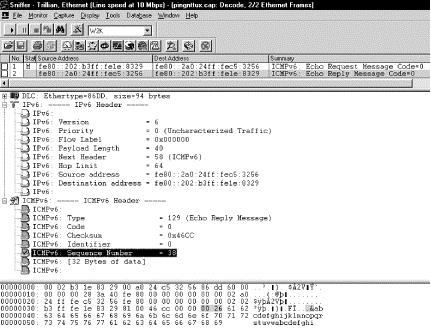
Figure 4-9. Echo Reply in a trace file
Again, the IPv6 header shows a value of 6 for the IP version and a Next Header value of 58 for ICMPv6. The destination address of the previous frame is now the source address, and the previous source address is now the destination address. The Type field in the ICMPv6 header shows a value of 129, which is the value for an Echo Reply. The Identifier and Sequence Number fields, as well as the Data field, match the ones in the Echo Request.
4.6 Neighbor Discovery
Neighbor discovery (ND) is specified in RFC 2461 (obsoletes RFC 1970). The specifications in this RFC relate to different protocols and processes known from IPv4 that have been modified and improved. New functionality has also been added. It combines Address Resolution Protocol (ARP) and ICMP router discovery and Redirect. With IPv4, we have no means to detect whether or not a neighbor is reachable. With the neighbor discovery protocol, a neighbor unreachability detection mechanism has been defined. Duplicate IP address detection has been implemented, too. IPv6 nodes use neighbor discovery for the following purposes:
•To determine layer 2 addresses of nodes on the same link
•To find neighboring routers that can forward their packets
•To keep track of which neighbors are reachable and which are not, and detect changed link-layer addresses
The following improvements over the IPv4 set of protocols can be noted:
•Router discovery is now part of the base protocol set. With IPv4, the mechanism needs to get the information from the routing table.
•Router advertisement packets contain link-layer addresses for the router. There is no need for the node receiving a Router Advertisement to send out an additional ARP request (as an IPv4 node would have to do) to get the link-layer address for the router interface. The same is true for ICMPv6 redirect messages; they contain the link-layer address of the new next-hop router interface.
•Router advertisement packets contain the prefix for a link (subnet information). There is no need to configure subnet masks anymore. They can be learned from the Router Advertisement.
48
•Neighbor discovery provides mechanisms to renumber networks easily. New prefixes and addresses can be introduced and old ones can be deprecated and removed.
•Router advertisements enable stateless address autoconfiguration and can notify hosts when to use stateful address configuration (e.g., DHCP).
•Routers can advertise an MTU to be used on a link.
•Multiple prefixes can be assigned to one link. By default, hosts learn all prefixes from the router, but the router can be configured not to advertise some or all of the prefixes. In that case, hosts assume that a non-advertised prefix destination is remote and send the packets to the router. The router can then issue ICMP redirect messages as needed.
•Neighbor unreachability detection is part of the base protocol. It substantially improves packet delivery in case of failed routers or link interfaces that changed their link-layer address. It solves the issues with outdated ARP caches. ND detects failed connectivity and traffic is not sent to neighbors that are unreachable. The neighbor unreachability detection also detects failed routers and switches to live ones.
•Router advertisements and ICMP redirects use link-local addresses to identify routers. This allows hosts to maintain their router associations even in the case of renumbering or use of new global prefixes.
•Neighbor discovery messages have a hop limit value of 255, and requests with a lower hop limit are not answered. This makes Neighbor discovery immune to remote hosts that try to sneak into your link because their packets have decremented hop limit and are thus ignored.
•The neighbor discovery protocol is used to detect duplicate IP addresses on a link.
•Standard IP authentication and security mechanisms can be applied to neighbor discovery.
This summary gives an idea of what can be expected from this part of the specification. Now let's discuss the different processes in detail. The neighbor discovery protocol consists of five ICMP messages: a pair of Router Solicitation/Router Advertisement messages, a pair of Neighbor Solicitation/Neighbor Advertisement messages, and an ICMP redirect message (refer to Table 4-2, earlier in this chapter, for a summary of ICMP informational message types).
4.6.1 Router Solicitation and Router Advertisement
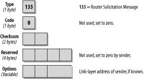
Routers send out Router Advertisement messages in regular intervals. Hosts can request Router Advertisements by issuing a Router Solicitation message. This will trigger routers to issue Router Advertisements immediately, outside of the regular interval. The format is shown in Figure 4-10.
Figure 4-10. Router Solicitation message
In the IP header of a Router Solicitation message, you will usually see the all-routers multicast address of FF02::2 as a destination address. The hop limit is set to 255. The ICMP Type field is set to 133, which is the value for the Router Solicitation message. The Code field is unused and set to 0. The following two Bytes are used for the Checksum. The next four Bytes are unused and reserved for future use. The sender sets them to 0 and the receiver ignores those fields. For a Router Solicitation message, valid Options are the link-layer address of the sending host, if known. If the source address on the IP layer is the unspecified (all-zeros) address, this field is not used.
49
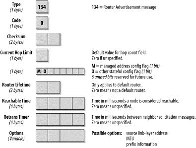
Routers that receive this Solicitation message reply with a Router Advertisement message. Routers also issue those messages periodically. The format of the Router Advertisement message is shown in Figure 4- 11.
Figure 4-11. Router Advertisement message
By inspecting the IP header of the Router Advertisement message, you can determine whether this Router Advertisement is periodic or was sent in reply to a Solicitation message. A periodic advertisement's destination address will be the all-nodes multicast address FF02::1. A solicited advertisement's destination address will be the address of the interface that originated the solicitation message. Again, the hop limit is set to 255.
The ICMP Type field is set to 134, the value for a Router Advertisement message; the Code field is unused and set to 0. The Current Hop Limit field can be used to configure all nodes on a link for a default hop limit. The value entered in this field will be used as a default hop limit value in outgoing packets by all nodes on the link. A value of 0 in this field means that this option is unspecified by this router—in which case, the default hop limit values of the source hosts are used.
The next 1-bit field, the M flag, specifies whether stateful configuration is to be used. Stateful configuration refers to what we know as DHCP with IPv4. If this bit is 0, the nodes on this link use autoconfiguration. If the bit is set to 1, it specifies stateful configuration. The O flag configures whether nodes on this link use stateful configuration for other than IP address information. A value of 1 means the nodes on this link use stateful configuration for non-address-related information. The remaining 6 bits of this byte are reserved for future use and must be 0.
The Router Lifetime field is important only if this router is to be used as a default router by the nodes on the link. A value of 0 indicates that this router is not a default router and will therefore not appear on the default router list of receiving nodes. Any other value in this field specifies the lifetime, in seconds, associated with this router as a default router. The maximum value is 18.2 hours.
The Reachable Time field is the time in which a host assumes that neighbors are reachable after having received a reachability confirmation. A value of 0 means unspecified. The neighbor unreachability detection algorithm uses this field.
The Retrans Timer field is used by the address resolution and neighbor unreachability detection mechanisms; it states the time in milliseconds between retransmitted Neighbor Solicitation messages.
50
