
IPv6 Essentials
.pdf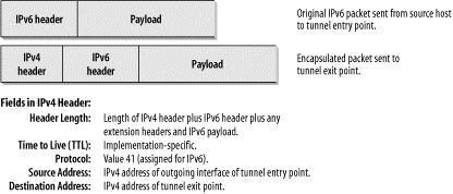
point is a host, the IPv6 destination address of the original packet is identical to the tunnel exit point and can be taken from the IPv6 header in the original packet. If the tunnel exit point is a router, the original packet's IPv6 destination address is not identical to the tunnel exit point address. In this case, the tunnel entry point must provide the address information to the tunnel exit point.
The steps for the encapsulation of the IPv6 packet are the following:
1.The entry point of the tunnel decrements the IPv6 hop limit by one, encapsulates the packet in an IPv4 header, and transmits the encapsulated packet through the tunnel. If necessary, the IPv4 packet is fragmented.
2.The exit point of the tunnel receives the encapsulated packet. If the packet was fragmented, the exit point reassembles it. Then the exit point removes the IPv4 header and processes the IPv6 packet to its original destination.
Figure 10-2 shows the encapsulation of an IPv6 packet in an IPv4 packet.
Figure 10-2. Encapsulation
The following fields in the IPv4 header are interesting to note: the Header Length field contains the length of the IPv4 header, plus the length of the IPv6 header, plus any extension headers and the length of the IPv6 payload. If the encapsulated packet has to be fragmented, there will be corresponding values in the Flags field and the Fragment Offset field. The value of the Time to Live (TTL) field depends on the implementation used. The Protocol Number is set to 41, the value assigned for IPv6. Thus, if you want to analyze your tunneled IPv6 traffic, you can set a filter in your analyzer to display the packets containing the value 41 in the Protocol Number field. The IPv4 Source Address is the address of the outgoing interface of the tunnel entry point and the IPv4 Destination Address is the IPv4 address of the tunnel exit point. The IPv6-over-IPv4 tunnel is considered a single hop. The hop limit field in the IPv6 header is therefore decremented by one. This hides the existence of a tunnel to the end user and is not detectable by common tools such as traceroute. Figure 10-3 shows an encapsulated IPv6 packet in the trace file.
171
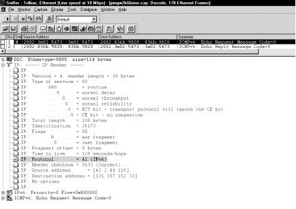
Figure 10-3. Encapsulation in the trace file
This is a ping generated on Marvin, our Windows 2000 host. We were pinging a host on the 6Bone. The TTL is set to 128. The Protocol field shows value 41 for IPv6, which identifies this packet as an encapsulated packet. The source address 62.2.84.115 is the IPv4 address of Marvin, which was configured for this address by a DHCP server. The destination address is the IPv4 address of a 6to4 relay router (6to4 concepts are explained in a separate section in this chapter) in the 6Bone, the tunnel exit point. This router can forward the packet to an IPv6 network, the 6Bone in this case. Compare these IPv4 addresses with the IPv6 source and destination addresses (which can be seen in the highlighted summary line above the detail screen).Use your Windows calculator to find out that the IPv6 source and destination addresses have the 6to4 prefix of 2002 plus the IPv4 address in hexadecimal notation in the low-order 32 bits. This is an example of a host-to-host automatic tunnel because we were actually pinging the 6to4 router.
If an IPv4 router from within the tunnel generates an ICMPv4 error message, the router sends the message to the tunnel entry point because that host is the source of that packet. If the packet contains enough information about the original, encapsulated IPv6 packet, the tunnel entry point may send an ICMPv6 message back to the original source of the packet.
When the tunnel exit point receives an IPv4 datagram with a protocol value of 41, it knows that this packet has been encapsulated. In case of fragmentation, it reassembles the packets, removes the IPv4 header, and delivers the IPv6 packet to the final destination.
Both tunnel end points need to have a link-local IPv6 address, with the IPv4 address of that same interface being the interface identifier for the IPv6 address. For example, a host with an IPv4 address of
192.168.0.2 has a link-local address of FE80::192.168.0.2/64.
Before forwarding a decapsulated IPv6 packet, the tunnel endpoint must verify that the tunnel source address is acceptable. Thus, unacceptable ingress into the network can be avoided. If the tunnel is a bidirectional configured tunnel, this check is done by comparing the source address of the encapsulated packet with the configured address of the other side of the tunnel. For unidirectional configured tunnels, the tunnel must be configured with a list of source IPv4 address prefixes that are acceptable. By default, this list is empty, which means that the tunnel end point has to be explicitly configured in order to allow forwarding of decapsulated packets.
172

10.2.2 Automatic Tunneling (RFC 2893)
Automatic tunneling allows IPv6/IPv4 nodes to communicate over an IPv4 infrastructure without the need for tunnel destination preconfiguration. The tunnel endpoint address is determined by the IPv4-compatible destination address. This type of IPv6 address is exclusively assigned to nodes that use automatic tunneling.
Figure 10-4 shows the output of the ipv6 if command on my Windows 2000 host Marvin.
Figure 10-4. The IPv4-compatible IPv6 address
The IPv4 address is 62.2.84.115. The IPv4-compatible address is created by taking the IPv4 address for the interface and prepending a 96-bit prefix of all zeroes. The interface to which this address is assigned is commonly called a pseudointerface. In the screenshot, this can be seen as ::62.2.84.115. An automatic tunnel is created by extracting the IPv4 address from the lower portion. As long as the IPv4 address used is not from the private range, the IPv4-compatible address is globally unique.
A special routing table entry can be used to direct packets through the tunnel. The entry would simply be a route to the all-zeros prefix with a 96-bit mask. All packets with an IPv4-compatible IPv6 address as a destination will match this prefix and be sent through the automatic tunnel. The destination IPv4 address is taken from the 32 low-order bits of the IPv6 destination address. The automatic tunnel must not send IPv4 packets to broadcast, multicast, loopback, or the unspecified address.
10.2.3 Configured Tunneling (RFC 2893)
In configured tunneling, the address of the tunnel exit point is configured on the tunnel entry point. When encapsulating the IPv6 packet, the tunnel entry point uses this address as the destination address in the IPv4 header.
IPv6/IPv4 hosts connected to network segments with no IPv6 routers can be configured with a static route to an IPv6 router in the Internet at the other side of an IPv4 tunnel; this enables communication with a remote IPv6 world. In this case, the IPv6 address of an IPv6/IPv4 router at the other end of the tunnel is added into the routing table as a default route. Now all IPv6 destination addresses match the route and can be tunneled through the IPv4 infrastructure. This default route has a mask of zero and is used only if there are no other routes with a more specific matching mask.
10.2.4 Combination of Automatic and Configured Tunneling
In many cases a combination of both tunneling techniques makes sense for IPv6/IPv4 hosts that are connected to segments with no IPv6 router. Such a host can have two routing entries for tunneling. One entry points to the all-zeros 96-bit prefix. All packets with IPv4-compatible IPv6 destination addresses will be sent through this route. The other routing entry points to an IPv6 router that is also configured to perform automatic tunneling. All packets with native IPv6 destination addresses will be routed through the configured tunnel. Reply packets from native IPv6 hosts will be sent to the IPv6 router, which delivers them back to the original host through automatic tunneling.
173
If a host sending a packet has both an IPv4-compatible IPv6 address and a global native IPv6 address, the host should use the IPv4-compatible address as a source address for packets to IPv4-compatible IPv6 destinations and use the native IPv6 address as a source address for packets to native IPv6 destinations.
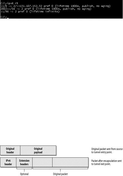
To summarize this, let's check the routing table on Marvin (Figure 10-5).
Figure 10-5. Marvin's routing table
The command used to display the routing table is ipv6 rt. The first entry is for ::/0. The zero-length prefix specifies this route as a default route. It is going out through interface number 2 with the next hop IPv6 address ::131.107.152.32. This is the IPv4-compatible IPv6 address of a 6to4 relay router that has been configured on Marvin. Thus, any IPv6 traffic that does not match a more specific routing entry is encapsulated in an IPv4 header and routed through this default route. Routing is enabled on Marvin; the associated lifetime and the published flag make this a published route. Interface number 2 is the tunnel pseudointerface (refer to Figure 10-4, which shows the interface configuration for the tunnel pseudointerface). All traffic going out through interface 2 is encapsulated in an IPv4 header. The entry for 2002::/16 is the route for the 6to4, also going out through interface 2 and being encapsulated. With these two routes, this host can reach the 6Bone and 6to4 hosts. The third routing entry specifies the route to the all-zeros prefix with a 96-bit mask, as discussed earlier. All IPv4-compatible IPv6 addresses match this prefix and will be routed through interface 2 if they don't match a more specific entry.
10.2.5 Encapsulation with IPv6 (RFC 2473)
RFC 2473 specifies the model and the generic mechanisms for encapsulation with IPv6. Most of the rules discussed in this chapter about tunneling in IPv4 apply to tunneling in IPv6. The main difference is that in tunneling in IPv6, the packets are encapsulated in an IPv6 header and sent through an IPv6 network. The packet being encapsulated can be an IPv6 packet, an IPv4 packet, or any other protocol. The tunnel entry point prepends the IPv6 header and, if needed, one or a set of Extension headers in front of the original packet header. Whatever the tunnel entry point prepends is called the Tunnel IPv6 headers. Figure 10-6 shows the Tunnel IPv6 headers from the packet view.
Figure 10-6. Tunnel IPv6 headers from the packet view
In the IPv6 header applied by the tunnel entry point, the source address is the address of the tunnel entry point node and the destination address is the address of the tunnel exit point node. The source node of the original packet can be the same node as the tunnel entry point. The original packet, including its header, becomes the payload of the encapsulated packet. The header of the original packet is treated according to standard forwarding rules. If the header is an IPv4 header, the TTL field is decremented by one. If it is an IPv6 header, the Hop Limit field is decremented by one. The network between the tunnel entry point and the tunnel exit point is thus virtually just one hop, no matter how many actual hops there are in between.
174

The Tunnel IPv6 header is processed according to the IPv6 protocol rules. Extension headers, if present, are processed as though the packet was a standard IPv6 packet. For example, a Hop-by-Hop Extension header would be processed by every node listed in the Hop-by-Hop Options field. A Destination Options header would be processed by the destination host—i.e., the tunnel exit point. All these options are configured on the tunnel entry point. An example of the use of a Destination Options header is the configuration of a Tunnel Encapsulation Limit Option (RFC 2473). This option may be used when tunnels are nested. One hop of a tunnel can be the entry point of another tunnel. In this case, we have nested tunnels. The first tunnel is called the outer tunnel and the second tunnel is called the inner tunnel. The inner tunnel entry point treats the whole packet received from the outer tunnel as the original packet and applies the same rules as shown in Figure 10-6. The only natural limit to the number of nested tunnels is the maximum IPv6 packet size. Every encapsulation adds the size of the tunnel IPv6 headers. This would allow for something around 1600 nested tunnels, which is not realistic. Also, consider the case in which the packet has to be fragmented. If it has to be fragmented again because the additional tunnel IPv6 headers have increased the packet size, the number of fragments is doubled. So a mechanism was needed to limit the number of nested tunnels. It is specified in RFC 2473 and is called the Tunnel Encapsulation Limit Option. This option is carried in a Destination Option header and has the format shown in Figure 10-7.
Figure 10-7. Format of the tunnel encapsulation limit option
The Option Type field has 1 byte and the decimal value 4, specifying the Tunnel Encapsulation Limit Option. The Option Data Length field has the decimal value 1, specifying the length of the following Option field. In this case, the Option field has a size of 1 byte and contains the actual value for the Tunnel Encapsulation Limit Option. The value in this field specifies how many further levels of encapsulation are permitted. If the value is zero, the packet is discarded and an ICMP Parameter Problem message is sent back to the source (the tunnel entry point of the previous tunnel). If the value is non-zero, the packet is encapsulated and forwarded. In this case, a new Tunnel Encapsulation Limit Option has to be applied with a value of one less than the limit received in the packet being encapsulated. If the packet received does not have a tunnel encapsulation limit but this tunnel entry point has one configured, the tunnel entry point must apply a destination options header and include the configured value.
Loopback encapsulation should be avoided. Loopback encapsulation happens when a node encapsulates a packet originating from itself and destined to itself. IPv6 implementations should prevent this by checking and rejecting configurations of tunnels where both the entry point and exit point belong to the same host. Another undesirable situation is a routing-loop nested encapsulation. This happens if a packet from an inner tunnel reenters an outer tunnel from which it has not yet exited. This can only be controlled by a combination of the original packet's hop limit plus the configuration of tunnel encapsulation limits.
Let's have a closer look at a Tunnel IPv6 Header (Figure 10-8).
175
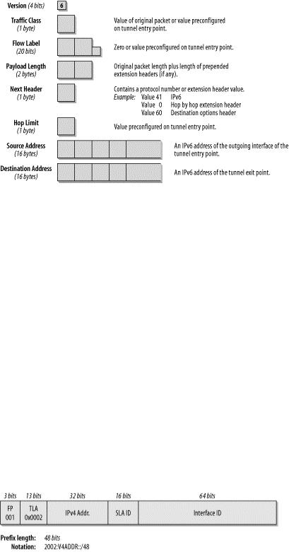
Figure 10-8. The tunnel IPv6 header
The fields of a standard IPv6 header were discussed in Chapter 2. Interesting values here are the following: the values for Traffic Class, Flow Label, and Hop Limit can be preconfigured on the tunnel entry point. The Payload Length has the value for the packet length of the original packet plus the size of any extension headers prepended by the tunnel entry point. The Source and Destination Address of the Tunnel IPv6 header contain the IPv6 addresses of the tunnel entry and exit point, respectively. Note that a host that is configured as a tunnel entry point must support fragmentation of packets that it encapsulates. Packets that are encapsulated may exceed the Path MTU of the tunnel. Because the tunnel entry point is considered the source of the encapsulated packet, it must fragment it if needed. The tunnel exit point node will reassemble the packet. If the original packet is an IPv4 packet with the Don't Fragment bit set, the tunnel entry point discards the packet and sends an ICMP Destination Unreachable message with the code "fragmentation needed and DF set" back to the source of the packet.
10.2.6 6to4 (RFC 3056)
RFC 3056, "Connection of IPv6 Domains via IPv4 Clouds," specifies a mechanism for IPv6 sites to communicate with each other over the IPv4 network without explicit tunnel setup. This is called 6to4. The wide area IPv4 network is treated as a unicast point-to-point link layer, and the native IPv6 domains communicate via 6to4 routers, also referred to as 6to4 gateways. This is intended as a transition mechanism used during the period of co-existence of IPv4 and IPv6. It will not be used as a permanent solution. The IPv6 packets are encapsulated in IPv4 at the 6to4 gateway. At least one globally unique IPv4 unicast address is required for this configuration. The IANA has assigned a special TLA for the 6to4 scheme. The address prefix is 2002::/16. Figure 10-9 shows the format of the 6to4 prefix in detail.
Figure 10-9. Format of the 6to4 prefix
The 32 bits after the prefix 2002::/16 are the IPv4 address of the gateway in hex representation. If you refer back to Figure 10-4, you can see how the IPv4 address 62.2.84.115 is converted to 2002:3e02:5473::/48. This leaves you with 80 bits of address space for your internal network. If you use, let's say, 16 bits for the local network addressing, you can create 65,536 networks! The remaining 64 bits can be used for the nodes on your network; that is, 264 nodes per network. It looks like getting
176

familiar with the extended address space has some advantages. Now all the hosts on your network can communicate with other 6to4 hosts on the Internet.
If your hosts want to speak to other IPv6 hosts on remote IPv6 networks, such as the 6Bone, you need a 6to4 relay router. The relay router is a router that is configured for 6to4 and IPv6. It connects your 6to4 network to the native IPv6 network.
There are a number of public 6to4 relay routers in the Internet that you can use. For a list, go to http://www.kfu.com/~nsayer/6to4/.
If you want to manually configure your 6to4 network for a 6to4 relay router, you can choose the best relay router for your site and use it as your IPv6 default route.
RFC 3068 defines a 6to4 relay router anycast address to simplify the configuration of 6to4 gateways that need a default route to find a 6to4 relay router on the Internet. IANA assigned an IPv4 6to4 Relay anycast prefix of 192.88.99.0/24. The assigned anycast address corresponds to the first node in the prefix, e.g., 192.88.99.1. The 6to4 routers have to be configured with a default route pointing to this anycast address. Using this address means that 6to4 packets are routed to the nearest available 6to4 relay router automatically. If one 6to4 relay goes down, you do not need to reconfigure your 6to4 gateway; packets will automatically be rerouted to the next available relay. With the ongoing deployment of IPv6 in commercial networks, the number of public 6to4 relay routers will increase. If a host wishes to communicate with a node on a native IPv6 subnet (i.e., destination address 3ffe:b00:c18:1::10), the IPv4 header destination address will be the reserved anycast address 192.88.99.1 and will be delivered to the nearest 6to4 relay router. In the reverse, a native IPv6 host that wants to send packets to a host that is in a 6to4 cloud will route its packets to the nearest 6to4 relay router advertising the prefix
2002::/16.
When IPv6 packets leave a 6to4 site to the external IPv4 cloud, they are encapsulated in IPv4 packets by the 6to4 gateway. Figure 10-10 shows the IPv4 header and the encapsulated IPv6 header in a trace file.
The TTL field in the IPv4 header and the Hop Limit in the IPv6 header are set to the value 128, which is a common default value for Microsoft. The IPv4 header contains a Protocol Type field of 41, for IPv6. The Source Address in the IPv4 header is the globally unique IPv4 address used for the 6to4 router configuration. The IPv4 destination address is the IPv4 address of the relay router used. When you compare the IPv4 addresses with the IPv6 6to4 addresses used, you can see how the translation is done.
177
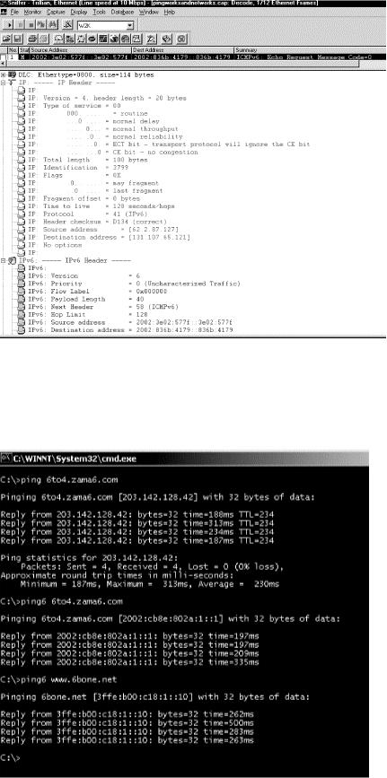
Figure 10-10. The IPv4 and IPv6 headers in the trace file
62.2.87.127 is represented with the prefix 2002:3e02:577f::/48, and
131.107.65.121 is represented as 2002:836b:4179::/48. Convert the decimal IPv4 address to hex and see how the IPv4 address is used for building the prefix.
Figure 10-11. Pinging the 6to4 relay and a 6bone node
178

If two hosts communicate—one with only a 6to4 address and the other one with a 6to4 address plus a native IPv6 address—the two hosts should both use the 6to4 address for communication. If both hosts have a 6to4 and a native IPv6 address, they should both use either the 6to4 address or the IPv6 address. Which choice is made should be configurable and the default should be IPv6.
Let me show you 6to4 in a simple example. In the public 6to4 relay router list mentioned earlier, I found that Zama Networks offers a public 6to4 relay with the DNS name 6to4.zama6.com. Note that this router is not there anymore, so don't try to use it. These are historic screenshots! Now let's find the address. The following pings were generated on my Windows 2000 host Marvin, which is configured for 6to4 (Figure 10-11).
The first ping is an IPv4 ping (ping.exe), which tells us that the 6to4 relay's IPv4 address is 203.142.128.42. The second ping is an IPv6 ping (ping6.exe) and shows that the IPv6 address is 2002:cb8e:802a:1::1. Thus, DNS resolution works for both record types. Again, if you convert the IPv4 address to hexadecimal, you get cb8e:802a. The next IPv6 ping goes to a 6Bone host, to www.6bone.net. It has the IPv6 address 3ffe:b00:c18:1::10. Note that the prefix 3ffe is the prefix assigned for 6Bone testing (refer to Chapter 3 for details about reserved prefixes).
10.2.7 ISATAP
The Intra-Site Automatic Tunnel Addressing Protocol (ISATAP) is designed to provide IPv6 connectivity between IPv6 nodes within a mainly IPv4-based intra-network that does not have an IPv6 router in the site. With ISATAP, you can deploy IPv6 in your corporate network, behind your firewall, even if you do not have an IPv6 router. ISATAP even allows you to use an automatic tunneling mechanism if you are using private IPv4 addresses and NAT. ISATAP addresses embed an IPv4 address in the EUI-64 interface identifier. ISATAP is still experimental and currently described in draft at http://www.ietf.org/internet- drafts/draft-ietf-ngtrans-isatap-04.txt. It is expected to become very popular.
Figure 10-12 shows the format of the ISATAP address.
Figure 10-12. The format of the ISATAP address
The ISATAP address has a standard 64-bit prefix that can be link-local, site-local, a 6to4 prefix, or belong to the global aggregatable unicast range. The Interface identifier is built using the IANA OUI 00 00 5E, which follows the prefix. The following byte is a type field, and the value FE indicates that this address contains an embedded IPv4 address. The last four bytes contain the IPv4 address, which can be written in dotted decimal notation. The format of the address can thus be summarized as 64bitPrefix:5EFE:IPv4address. For instance, if you have an assigned prefix of 2001:620:600:200::/64 (guess where that is) and an IPv4 address of 62.2.84.115, your ISATAP address is 2001:620:600:200:0:5EFE:3e02:5473. Alternatively, you can write 2001:620:600:200:0:5EFE:62.2.84.115. The corresponding link local address would be
FE80::5EFE:62.2.84.115.
Using ISATAP, IPv6 hosts within an IPv4 intranet can communicate with each other. There is no need for an IPv6 router. If they want to communicate with IPv6 hosts on the Internet, such as 6Bone hosts, a border router must be configured; it can be an ISATAP router or a 6to4 gateway. The IPv4 addresses of all the hosts within the site do not need to be public. They are embedded in the address with the standard prefix and are therefore unique and routable. Large numbers of ISATAP hosts can be assigned to one ISATAP
179
prefix. If you deploy IPv6 on a segment in your corporate network, you can configure one of the native IPv6 nodes with an ISATAP interface, and it can act as a router between the native IPv6 segment and ISATAP hosts in the IPv4 segments. Because the ISATAP nodes on the IPv4 network do not have an IPv6 router that can send them prefix information for autoconfiguration, they currently need to be configured for the prefix and need a default route pointing to the ISATAP router or 6to4 gateway if connectivity to the Internet is required. The ISATAP draft explains mechanisms that are in development to allow automatic intrasite IPv6 router discovery and stateless address autoconfiguration. An ISATAP router anycast address is in discussion and would work the same way as explained for the 6to4 anycast address described earlier in this chapter.
10.2.8 Teredo
6to4 makes IPv6 available through the IPv4 infrastructure. ISATAP enables deployment of IPv6 hosts within a site without the need for IPv6 routers. Teredo (called Shipworm in earlier drafts) is another mechanism under development. It is designed to make IPv6 available to hosts through one or more layers of NAT, which cannot be upgraded to 6to4, by tunneling packets over UDP. Teredo servers and Teredo relays are needed to make the service work. Teredo is in draft status, and many details still need to be defined. If you are interested in following the process, refer to http://www.ietf.org/internet-drafts/draft-ietf- ngtrans-shipworm-06.txt. Note that the draft number may have increased by one or more when you go there.
10.2.9 A Sample Network Design
I will discuss a sample network design to summarize the tunneling concepts and give you a picture of a possible scenario. You will see that you can start to deploy IPv6 step by step on single hosts or subnets and that there is no requirement to change your whole IPv4 infrastructure overnight. If you are familiar with setting up NAT for your IPv4 network, these concepts will not be too difficult to master.
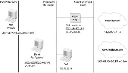
Figure 10-13 shows a 6to4 scenario.
Figure 10-13. A 6to4 design
Marvin is your company's 6to4 gateway. It is connected to the Internet with a routable IPv4 address of 62.2.84.144 and has a logical IPv6 interface into the corporate network advertising the 2002:3e02:5490::/48 prefix for the 6to4 route. It has been configured with the IPv4 address of a 6to4 relay router, in this case 6to4.zama6.com. This 6to4 gateway (Marvin) provides IPv6 transit for all IPv6 machines from within the corporate network. Ford is an IPv6-only machine within the network. It has autoconfigured its IP address of 2002:3e02:5490:2a0:24ff:fec5:3256 using the prefix advertised by Marvin. The 6to4 relay router used in this example is the public relay offered by Zama
180
