

IPv6 Essentials
.pdfFigure 8-32. External routes for router R1
The calculation of the OSPF routing table is now finished, and its content is handed to the internal routing process of the router.
8.2.7 LSA Flooding
Any change in the network causes certain link state information to change. Examples of such changes include the following:
•The state of a router's interface changes.
•A neighbor transitions from or to full state.
•The DR changes.
•A new prefix is added or deleted on any given interface.
•An area's summary information changes.
•An external route is added or withdrawn at the ASBR.
The router detecting the change rewrites the LSA accordingly, increases the sequence number, and gives the LSA to the flooding process. According to Table 8-5, the LSA is then flooded to a neighbor only (link scope), to all neighbors in the same area (area scope), or to all neighbors (AS scope).
Flooding means that the LSA is passed from the advertising router to its adjacent neighbors. Depending on the flooding scope of the LSA, the neighbors then pass it on to their neighbors, and so on. Each router receiving an LSA first evaluates whether the LSA is new or has a higher sequence number than the one already installed in the LSDB. If either of these two conditions is true, the LSA is added or replaced in the LSDB. Now the router considers the interfaces to be used for further flooding. It will not flood the LSA out the incoming interface, with one exception: if the router is a DR for the incoming interface of the LSA and the LSA was not sent by the BDR, it must be flooded back out the same interface. The DR is responsible for sending LSAs to all its neighbors. Another reason not to flood the LSA is if the LSA is older than or the same age as the one already installed. This prevents LSAs from looping in the network. LSAs are normally sent to the multicast address AllSPFRouters, with the following exceptions:
141
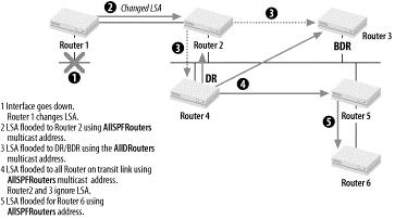
•On transit networks, routers in the DR-Other state send LSAs to the address AllDRouters. The update reaches the DR/BDR, which in turn sends it back to all other routers on this transit link using the AllSPFRouter address.
•If a router requests a link state update sending a Link State Request packet, the LSA uses the unicast address of the requesting router.
•On NBMA, all LSAs are sent unicast to the statically configured neighbors.
Figure 8-33 shows the process of a DR receiving new or changed LSAs and flooding them to all routers.
Figure 8-33. LSA flooding
Each router receiving a new or changed LSA has to acknowledge this LSA. Sending a Link State Acknowledgment packet usually accomplishes this. It could also be acknowledged by sending back the LSA if the received LSA is older or the same age as the one already installed in the LSDB. In that case, the sequence number is set to the one already installed. Unacknowledged LSAs have to be retransmitted. Each router keeps track of which neighbor has acknowledged which LSA. Retransmissions are always sent to the unicast address of the neighboring router.
A sequence number is assigned to the LSA by the advertising router to keep track of the most recent instance of this particular LSA. The sequence number is incremented by the advertising router each time the LSA is changed. When a new or changed Router-LSA or Network-LSA is received and accepted, the router installs it in the LSDB. It then recalculates the SPF tree. If a new or changed LSA of another type is received, it is not necessary to recalculate the SPF tree because these LSAs represent informational pointers only. They replace or remove the existing information. The new information is used to reevaluate the best path for the intra-area, inter-area, or external routers.
8.2.7.1 Aging an LSA
In addition to the sequence number, each LSA maintains an Age field. The age is expressed in seconds. Each router increments the Age field of its LSA continuously. If an LSA is transmitted to the neighbor router, a transmit delay must be added to the Age field. An LSA can never age beyond a Maximum Age (MaxAge), which is an architectural constant set to 3,600 seconds. Usually a router is flooding a new instance (increment sequence number) of its own LSA when it has reached MaxAge/2. LSAs that have reached MaxAge are not considered for the SPF tree and are eventually deleted from the LSDB. The advertising router can prematurely age an LSA to flush it from the OSPF area or AS. This would be done if, for example, an external route was withdrawn. Another reason to prematurely age an LSA might occur if the LSA has reached the biggest sequence number possible. Before wrapping the sequence number (starting again), the LSA has to be flushed.
142
8.2.7.2 Self-originating LSAs
A router may receive an LSA that it has issued itself. This could happen if there are redundant links within the area, forming a loop. Self-originated LSAs are normally discarded, unless the self-originated LSA is newer. Obviously, this should not happen because only the advertising router can increment the sequence number of the LSA. If, however, the router has been rebooted, previously issued LSA are still held in the other router's LSDB. If a newer, self-originated LSA is received, the router prematurely ages that LSA, thereby flushing it from the area or AS.
8.2.7.3 Handling of unknown LSAs
OSPF for IPv6 has added the capability to handle unknown LSAs. Each LSA header contains the U bit in its LSA Type field. If the U bit is set, the unknown LSA is flooded according to the encoded flooding scope. A U bit set to zero indicates link-local flooding scope. The exception to the above rule is flooding into a stub area. AS-External-LSAs are never flooded into a stub area. To prevent unnecessary flooding of LSAs into a stub area, the following rule applies: if the LSA is unknown and either its flooding scope is set to AS or its U bit is set, the LSA is discarded and not flooded into a stub area.
8.3 BGP Extensions for IPv6
There is no actual BGP for IPv6. The IPv6 support derives from the capability of BGP-4 to exchange information about network layer protocols other than IPv4. These multiprotocol extensions of BGP-4 are defined in RFC 2858, which obsoletes RFC 2283. RFC 2283 is mentioned here because it is the base document for RFC 2545, which defines the IPv6 extensions of BGP-4. It is important to understand BGP-4 fully before looking at its multiprotocol extensions. The following sections start with a short overview of BGP-4 and its operations as defined in RFC 1771. BGP message types are then discussed. The last part covers the implementation of IPv6 information carried within BGP-4.
8.3.1 BGP-4 Overview
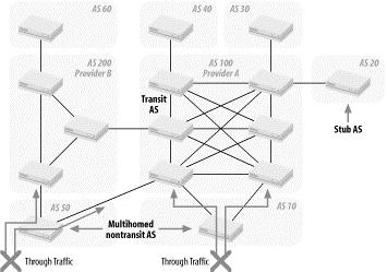
Each AS runs its interior routing protocol (RIP, OSPF, etc.) to distribute all routing information within the AS. The BGP is an exterior routing protocol whose primary function is to exchange information about the reachability of networks between ASes. Each AS receives a unique AS number assigned by the numbering authority. Figure 8-34 shows the different types of ASes that can be interconnected using BGP-4.
Figure 8-34. BGP traffic and AS types
The AS types are further explained in the following list:
143
Transit AS
A transit AS has multiple connections to other AS. Routing updates from any AS arriving at the transit AS may be passed through the AS and distributed out to other neighboring ASes. A transit AS can forward traffic to any other ASes based on the routing information received. The ASes of larger ISPs are usually of this type.
Stub AS
A stub has a single connection to another AS. All traffic to or from the stub AS passes through this link. Smaller ISPs and campus or corporate networks use this kind of AS.
Multihomed nontransit AS
A multihomed nontransit AS has multiple connections to one or more other AS. It does not pass routing updates through. Traffic not belonging to this AS is therefore never forwarded. A multihomed nontransit AS allows multiple entry/exit points to be used for load sharing of inbound and outbound traffic.
Two routers exchanging routing information with BGP are called BGP Peers or BGP speakers. They establish a TCP session first because TCP guarantees a reliable connection. The peers then open a BGP connection to exchange BGP messages. The most important BGP message is the UPDATE message, which contains the routes to be exchanged. A BGP route is defined as a unit of information consisting of the Network Layer Reachability Information (NLRI) and a set of path attributes. The NLRI is basically an IPv4 prefix and its prefix length. Any concept of IPv4 class information has been eliminated. The NLRI may represent a single network or, more commonly, an aggregate (summary) of a range of addresses. Each NLRI is accompanied by a set of path attributes that add additional information to the BGP route, i.e., the next hop address, a sequence of ASes through which the route has passed during its update, or its origin. Routing decisions and traffic management are often based on these path attributes. One attribute must be emphasized here, as it plays a very important role in loop detection:it is called AS_PATH, and it carries a sequence of AS numbers through which the route has passed. If the receiving peer recognizes its own AS number within the AS_PATH, it rejects the corresponding route.
BGP routing updates are exchanged between two peers. They are governed by a set of rules called policies. Outbound policies specify which NLRIs are advertised to a particular peer. A router can advertise only the NLRI it uses itself. Inbound policies specify which NLRIs are accepted from a particular peer. Policies may also be used to modify an NLRI and its attributes to change the characteristics of a route.
8.3.1.1 Establishing a BGP connection
In order to exchange routing updates, two peers first have to establish a BGP connection. Figure 8-35 illustrates the steps needed to establish a BGP connection, including the different BGP messages exchanged and the peer state. The entire state machine is explained in detail in RFC 1771. Each message and its fields are explained in Section 8.3.2.
144
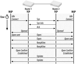
Figure 8-35. Establishing a BGP connection
If both routers simultaneously try to establish a BGP connection to each other, two parallel connections might well be formed. To avoid this connection collision, one router has to back down. The connection initiated by the router with the higher BGP Identifier prevails. The BGP Identifier is uniquely assigned to each BGP router and is exchanged during the OPEN message. Once the open is confirmed, the routers exchange the entire routing table based on their policies. Only changes in the routing table are exchanged from now on. KEEPALIVE messages prevent the connection from timing out. The TCP session guarantees reliable delivery of each packet.
BGP distinguishes between the following peer connections:
IBGP connection
The peers are in the same AS and are called internal peers. BGP routes learned from internal peers must not be sent back to other internal peers; they can only be sent to external peers. Each internal peer must have a connection to all other internal peers. Internal peers are fully meshed. The introduction of AS confederation for BGP (RFC 3065) or BGP route reflection (RFC 2796) relaxes the above rule. The AS_PATH and NEXT_HOP attributes must not be modified when passing updates to internal peers.
EBGP connection
The peers are in different ASes and are called external peers. BGP routes learned from external peers can be updated to all other peers. When sending an update to an external peer, the AS_PATH and NEXT_HOP attributes are modified. The sending router adds the local AS number to the AS_PATH and sets the NEXT_HOP field to its local IPv4 address.
NOTIFICATION messages inform the peers of any errors during the open or update process. The connection can be shut down gracefully using a cease NOTIFICATION message.
8.3.1.2 Route storage and policies
BGP routes are stored in a Routing Information Base (RIB). Figure 8-36 shows the three different RIBs and their interaction.
145
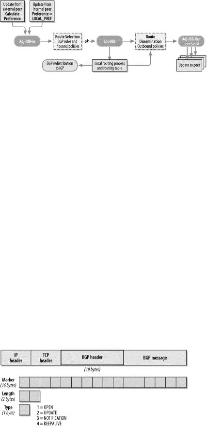
Figure 8-36. BGP RIBs and its interactions
Incoming messages could contain new feasible routes, replacement routes of earlier updates, or routes that have been withdrawn by the advertising peer. All these routes are placed into the Adj-RIB-In. For each new or changed route, a degree of preference is calculated based on the inbound policy. This preference is placed into the attribute LOCAL_PREF. If the route arrives from a internal peer, the LOCAL_PREF is already carried in the update and should not be recalculated. Each route in the Adj-RIB-In is now processed by the route selection process and entered into the Loc-RIB. The selection process first looks at the NEXT_HOP and AS_PATH attributes of the route. The IP address specified by the NEXT_HOP must be reachable through an entry in the local routing table. The AS_PATH must not contain the local AS number. If the two attributes comply, the route is accepted or ignored based on the inbound policy; otherwise, the route is ignored. In case of multiple routes to the same destination, the route with the highest preference is accepted. In case of the same preference, a complex tie-breaking rule ensures that only one of the routes to the same destination is accepted. See RFC 1771 for more details on this tie-breaking rule.
Routes in the Loc-RIB are now placed into the local routing table. The true next hop address is taken from the local route entry to the IPv4 address specified in the NEXT_HOP attribute.
All routes in the Loc-RIB and all routes in the local routing table are eligible to be advertised to external peers of this router. Only routes in the Loc-RIB learned from external peers are eligible to be advertised to all internal peers of this router unless route reflection is enabled (see RFC 2796). The outbound policy disseminates the routes to a peer-specific Adj-RIB-Out. The outbound policy may perform route aggregation or path attribute modification. Changes in the Adj-RIB-Out cause the update process to send an update to the peer.
8.3.2 BGP Message Header
BGP messages are carried on top of TCP connections, which can be established either over IPv4 or IPv6. The source and destination IP addresses of the datagram depend on the peer configuration. They are always unicast. BGP connections use the well-known TCP port 179. Remember that only one TCP connection is established between two peering routes. Figure 8-37 shows the BGP message header format. The header has a fixed size of 19 bytes.
Figure 8-37. BGP message header format
146
The fields of the BGP header are explained in detail in the following list:
Marker (16 bytes)
Contains authentication data if authentication was negotiated between the peers. All bits are set to one if no authentication is used or in the OPEN message.
Length (2 bytes)
The total length of the BGP message, including headers. The value must be between 19 and 4096. The maximum message size of any BGP message is 4096 bytes.
Type (1 byte)
Indicates the BGP message types, as listed in Table 8-9.
Table 8-9. BGP message types
Type |
Name |
Description |
1 |
OPEN |
Initializes BGP connection and negotiates session parameters |
2 |
UPDATE |
Exchanges feasible and withdrawn BGP routes |
3 |
NOTIFICATION |
Reports errors or terminates BGP connections |
4 |
KEEPALIVE |
Keeps the BGP connection from expiring |
8.3.3 OPEN Message
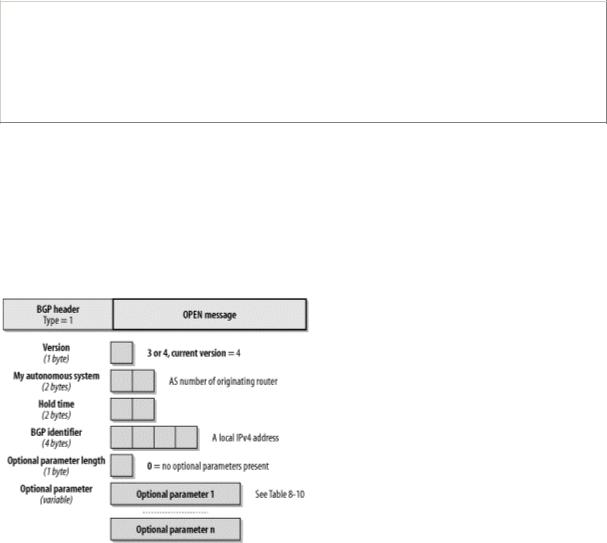
As soon as the TCP connection between two BGP peers has been established, the routers send OPEN messages to initialize the BGP connection. This message verifies the validity of the peer and negotiates parameters used for the session using the fields illustrated in Figure 8-38. To verify the validity of a peer, each side of the connection must configure the IP address and the AS number of the peer.
Figure 8-38. The BGP OPEN message
The fields of the OPEN message are detailed in the following list:
Version (1 byte)
147
Indicates the BGP version used by the sending peer. The current version is 4. Both peers have to agree on the same version. The version can be negotiated. Each peer usually indicates the highest version it supports. If the receiving peer does not support this version, it notifies the peer and terminates the session.
My Autonomous System (2 bytes)
Indicates the AS number of the sending router. The receiving router must verify this number to be the peer's AS number. If it is incorrect, the peer is notified and the session is terminated. If the AS number is the same as the receiving router's AS number, the peer is internal (IBGP); otherwise, the peer is external (EBGP).
Hold time (2 bytes)
Proposes a maximum time in seconds that may elapse before any BGP message must arrive on this interface. The hold timer is negotiated to the smaller value advertised by either peer. To keep a BGP connection from expiring, the peers send KEEPALIVE messages once every HoldTime/3 second. A hold time of zero indicates that no KEEPALIVE messages need to be sent. The value of the hold time is 0 or greater than 2.
BGP Identifier (4 bytes)
Each router must be identified by a unique, globally assigned BGP identifier. At startup, the BGP Identifier is set to an IPv4 address of a local interface. This means the router must a have at least one IPv4 address configured locally, even in an IPv6-only environment. The message is rejected if the BGP Identifier equals the BGP Identifier of the receiver or if the BGP Identifier is illegal. During route selection, the BGP Identifier may be used to break a tie.
Optional Parameter Length (1 byte)
Indicates the length of optional parameters to be negotiated. A length of zero indicates that there are no optional parameters.
Optional Parameters
Each Optional Parameter consists of a <Type, Length, Value> (TLV) triplet. Both routers must know and agree on the optional parameter; otherwise, the peer is notified of the rejection of the parameter. This could lead to the termination of the session. At the moment, two parameters are specified, as explained in Table 8-10. The optional parameter BGP Capability is very important for IPv6 support.
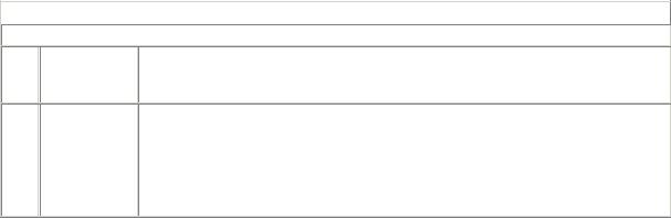
Table 8-10. Optional parameters
Type
 Name
Name 
 Description
The parameter consists of two fields: Authentication Code and Authentication Data. 1 Authentication The Authentication Code defines the authentication mechanism used and how the
marker and authentication data field are to be computed.
2BGP Capability
The parameter consists of one or more <Code, Length, Value> triplets identifying different BGP Capabilities. It is defined in RFC 2842. The capability parameter may appear more than once in the OPEN message.
The Capability Code set to 1 indicates the Multiprotocol Extension Capability, as defined in RFC 2858.
148
The Multiprotocol Extension Capability has a 4-byte value field. The first 2 bytes identify the Address Family Identifier (AFI), byte 3 is reserved, and byte 4 defines the Subsequent Address Family Identifier (SAFI). AFI defines the network layer protocol used in the multiprotocol extension. SAFI defines additional information about the protocol, such as whether the protocol uses unicast forwarding (SAFI=1), multicast forwarding (SAFI=2), or both (SAFI=3). To support IPv6, the Multiprotocol Extension Capability is set to <Code=1, Length=4, Value=hexadecimal 0x0002 0001).
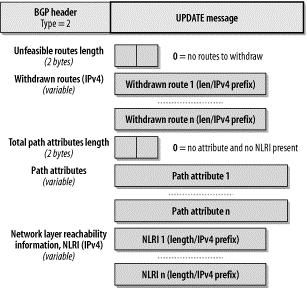
8.3.4 UPDATE Message
An UPDATE message carries BGP route(s) advertised by the originating peer. It is divided into three sections, as outlined in Figure 8-39. The first section specifies the IPv4 NLRI that the sending peer is withdrawing. The second section defines all path attributes associated with the feasible IPv4 NLRI followed in section three. Multiple NLRI with the same exact same set of path attributes can be placed in a single UPDATE message.
Figure 8-39. The BGP UPDATE message
The fields of the UPDATE message are detailed in the following list:
Unfeasible Routes length (2 bytes)
Defines the length of the Withdrawn Routes field. Set to zero, it indicates that the originating peer has no route to withdraw with this message.
Withdrawn Routes
A list of IPv4 NLRIs that are no longer valid. Each NLRI is encoded as <length, prefix> and represents an IPv4 prefix. The 1-byte Length field defines the length of the corresponding Prefix field. The Prefix field is padded to the full octet with zero bits. Because the NLRIs are IPv4 prefixes, this field can never be used to withdraw IPv6 routes. See Section 8.3.7 for further details.
Total Path Attribute length (2 bytes)
Defines the length of the Path Attributes field.
149
Path attributes
Contains a list of path attributes that belong the feasible NLRI advertised. Attributes are further explained in Section 8.3.5.
Network Layer Reachability Information
A list of IPv4 NLRIs that are advertised with this update. Each NLRI is encoded as <length, prefix> and represents an IPv4 prefix. The 1-byte Length field defines the length of the corresponding Prefix field. The Prefix field is padded to the full octet with zero bits. The total length of this field is calculated as follows:
UPDATE message length-23-Unfeasible Routes Length-Total Path Attribute Length
Because the NLRIs are IPv4 prefixes, this field can never be used to advertise IPv6 routes. See Section 8.3.7 for further details.
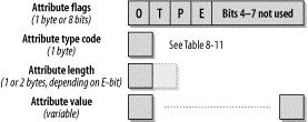
8.3.5 BGP Attributes
Path attributes provide additional information about the advertised NLRI. Each path attribute has a 2-byte attribute header, as depicted in Figure 8-40.
Figure 8-40. The BGP path attributes
The Path Attribute header is explained in detail in the following list.
O bit (Optional bit)
Defines whether the attribute is optional (set to one) or well known (set to zero). A well-known attribute must be recognized and supported by each BGP router. Optional attributes may not be recognized by some routers.
T bit (Transitive bit)
Defines whether the attribute is transitive (set to one) or nontransitive (set to zero). Transitive attributes must always be passed on when the NLRI is advertised to another peer. Well-known attributes must always be transitive.
P bit (Partial bit)
Applies to optional transitive attributes only. If any router along the update path does not recognize the optional transitive attribute, it must set the P bit to one. This indicates that at least one router in the path to the route does not recognize this attribute. This bit must always be set to zero for optional nontransitive or well-known attributes.
150