


Chapter 15
Fixed prosthetic restoration in edentulous patients has concerned researchers for many years. Various types of implants were manufactured for this purpose, without yielding the expected results, while being criticized by many, mainly because of the infections they caused. For a long time, the placement of most implants was a failure. This failure was attributed to inadequate research data, but also to the fact that the whole implant procedure was not based on biological principles, which are mandatory for the long-term success of implants in the oral cavity.
Nowadays osseointegrated implants are used, which have been proven to be totally biocompatible.
Osseointegration refers to the immediate structural, biological, and functional connection between metal implants and healthy bone, without soft, noncalcified connective tissue intervening, so that the bone may remodel and adjust to the load-bearing implants.
15.1 Indications
The indications for placement of osseointegrated implants include:
ΟPatients who cannot be treated using other techniques (compromised retention of denture, defects of the jaw).
ΟPatients who benefit from dental implants compared to the conventional therapy (edentulous, shortened arch, single crowns, orthodontic retention).
ΟPatients who have comparable functional outcome using dental implants or a conventional therapy. In these cases subjective personal or esthetic reasons may justify the implant therapy.
Osseointegrated Implants |
15 |
F. D. Fragiskos, C. Alexandridis |
|
|
|
15.2 Contraindications
The contraindications for placement of implants are the same as for all other dental surgical procedures.
15.3 Instruments
The instruments used for the placement of screw-type implants are the following:
1.Surgical micromotor with handpieces (Fig. 15.1)
2.Titanium and stainless steel instruments, which are separated and placed in a special tray during the surgical procedure (Fig. 15.2)
15.4
Surgical Procedure
The placement of osseointegrated implants includes two stages: the first is the principal surgical procedure of implanting, while the second entails exposure of the implants and installation of the abutments on the implant body, which will then support the prosthetic restoration.
The first stage includes the following:
Creation of Flap. In the edentulous mandible, and after administration of an inferior alveolar nerve block, an incision is made using a no. 15 scalpel blade at the depth of the mucolabial fold, which inclines towards the alveolar crest in the region of the mental foramina. The mucoperiosteum is reflected until the alveolar crest is exposed between the canines, while part of the alveolar crest is also exposed lingually.
In an edentulous maxilla, after administration of bilateral nerve blocks of the anterior superior alveolar nerve, nasopalatine nerve, as well as infiltration anes-
338 F. D. Fragiskos, C. Alexandridis
Fig. 15.1. Surgical micromotor appropriate for placement of implants
Fig. 15.2. Set of instruments for placement of osseointegrated implants
thesia labially or buccally and palatally, a straight incision is made labially or buccally, at two-thirds the height of the alveolar crest or on top of the crest itself.
The incision then extends from the region of the right
first molar until the respective area of the opposite side (Fig. 15.3). The flap is adequately reflected towards the labial or buccal and palatal bone surface, so that there is adequate visualization and access to the surgical field (Fig. 15.4).
Preparation of Implant Recipient Site by Drilling at High Speed. The first bur used to prepare the bone is the round guide bur. This bur is used to initially drill (at high speed, approximately 2000 rpm) all of the implant recipient sites very carefully, after taking into consideration the anatomy and topography of the jaw area (Fig. 15.5). Drilling of the bone is performed with constant irrigation of saline solution, while the bur must move in an up-down direction, so that the saline solution may reach the depth of the implant recipient site. The bone chips are thus removed, while bonedamaging heat buildup is also prevented.
A spiral bur with a diameter of 2 mm is then used to prepare the implant recipient sites. There are markings on the surface of the bur indicating suitable preparation depths for the various implant recipient sites. The dentist must pay particular attention at this stage so that the bur is positioned in the right direction in order to avoid perforation of the bone buccally or palatally. A paralleling pin is then placed in the recipient site, serving as a guide for the gradual preparation of the rest of the recipient sites, so that they are parallel to each other (Fig. 15.6).
In some cases a pilot bur with a diameter of 2–3 mm can be used to widen the implant recipient sites, and the paralleling pins are successively removed (Fig. 15.7 a).
The next stage of widening the implant recipient sites is achieved using a longer twist bur, also with a diameter of 3 mm. The entire length of the recipient sites is widened with this bur and the paralleling pins are consecutively placed once again (Fig. 15.7 b, c).
A marginal countersink with a conical shape can often be used to prepare the shelf for installation of the implant (Fig. 15.8) if the implant site is in an esthetically relevant position.
Preparation of Threads in Implant Recipient Site by Drilling at Low Speed (Required by Only a Few Systems). This stage involves the preparation of threads inside the recipient site by drilling at low speed (15–20 rpm). The entire procedure is performed using the screw tap bur, which, after being inserted in the contra-angle handpiece, prepares the threads at the implant recipient site in bone, at a depth that corresponds to the length of the implant to be placed (Fig. 15.9).
Chapter 15 Osseointegrated Implants |
339 |
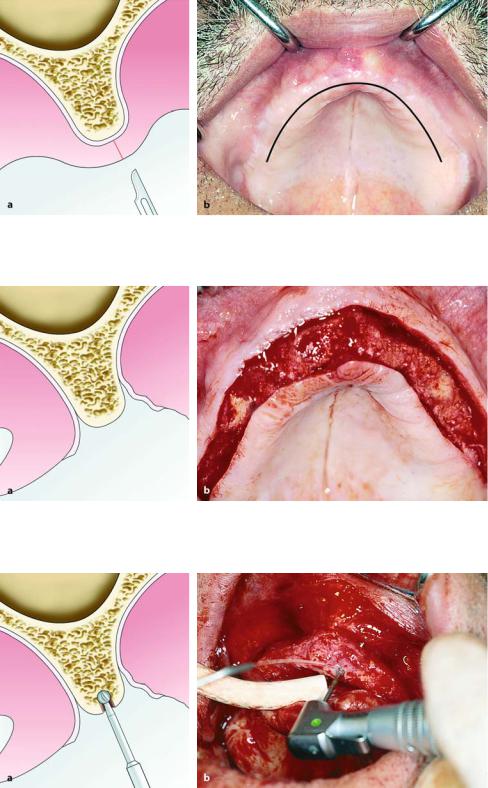
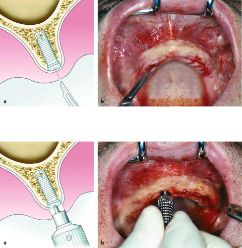
Fig. 15.3 a, b. Surgical procedure for placement of Branemark implants in maxilla. Diagrammatic illustration (a) and clinical photograph (b) showing planning of incision for creation of appropriate flap
Fig. 15.4 a, b. Reflection of flap and exposure of bone where implants are to be placed. a Diagrammatic illustration. b Clinical photograph
Fig. 15.5 a, b. Guide drill preparation at cortical bone using round bur. a Diagrammatic illustration. b Clinical photograph
340 F. D. Fragiskos, C. Alexandridis
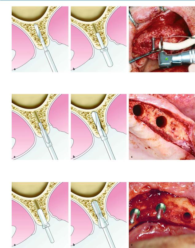
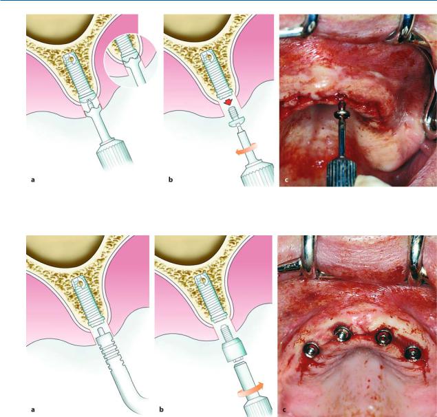
Fig. 15.6 a–c. Preparation of initial recipient site with a 2-mm-diameter bur and placement of paralleling pin. a, b Diagrammatic illustrations. c Clinical photograph
Fig. 15.7 a–c. a Initial widening of bone recipient site with a 3-mm pilot bur. b, c Completion of preparation of recipient site with 3-mm-diameter standard twist bur
Fig. 15.8 a–c. Placement of respective paralleling pin at recipient site in bone, and creation of bevel or countersink margin with conical bur. This bur is used to prepare
the shelf for the cervical portion of the implant within the marginal compact layer of bone. a, b Diagrammatic illustrations. c Clinical photograph
Chapter 15 Osseointegrated Implants |
341 |
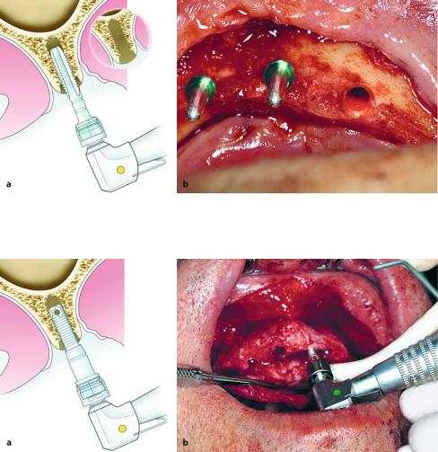
Fig. 15.9 a, b. Threaded implant recipient site prepared with screw tap bur. a Diagrammatic illustration. b Clinical photograph
Fig. 15.10 a, b. Installation of implant by way of screwing into prepared recipient site at bone. a Diagrammatic illustration. b Clinical photograph
Installation of Implant and Placement of Cover Screw. In this step, the implant is adapted to the receiver of the implant mount, which has been placed in the low-speed contra-angle handpiece and is transferred to the implant recipient site. The first implant is placed in the left distal site. Irrigation with saline solution is not permitted until the lower border of the implant is installed well within the implant recipient site in the bone, so that the saline solution will not be compressed into the medullary bone by the implant. The implant is screwed into the bone without pressure, until the engine of the handpiece stops on its own (Fig. 15.10). Afterwards, a cylinder wrench is used to screw the implant manually as far as the deepest part of the recipient site (Fig. 15.11). The implant mount is removed either by hand using a screwdriver, or mechanically with a screwdriver attached to the low-
speed contra-angle handpiece. A paralleling pin is screwed in the canal of the first implant installed, and the rest of the implants are then placed.
In the final step, a cover screw is placed, which covers the horizontal surface of each implant, thus preventing intervention or proliferation of the mucosal tissues inside the implant (Fig. 15.12). Final tightening must be done by hand, being careful that it is not so tight that removal is rendered difficult in the second stage of surgery. The same procedure is followed for the rest of the implants.
Copious irrigation with saline solution is then performed, and the flap is repositioned and sutured with interrupted sutures (Fig. 15.13). As for the surgical procedure, antibiotics are administered prophylactically
(preoperatively), as well as analgesics for management of postoperative pain. The sutures are removed 7 days
342 F. D. Fragiskos, C. Alexandridis
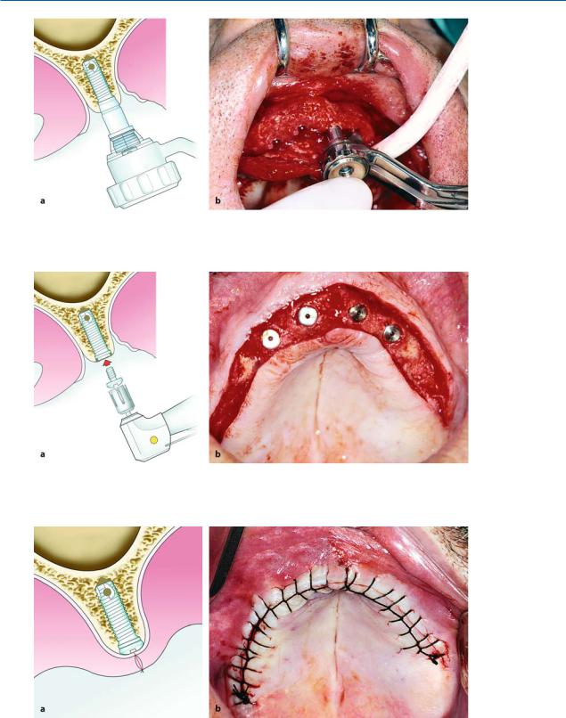
Fig. 15.11 a, b. Continuation of insertion manually with cylinder wrench, until implant reaches deepest part of recipient site. a Diagrammatic illustration. b Clinical photograph
Fig. 15.12 a, b. Placement of cover screw over implant, to preventing intervention or proliferation of mucosal tissues inside implant. a Diagrammatic illustration. b Clinical photograph
Fig. 15.13 a, b. Operation site after repositioning and suturing of flap. a Diagrammatic illustration. b Clinical photograph
Chapter 15 Osseointegrated Implants |
343 |
after the operation. The healing phase varies depending on the primary stability of the implants and the prosthetic reconstruction. Immediate loading of implants often is possible in splinted restorations and in the hard bone of the mandible. Usually a healing time of 8 weeks is recommended by the manufacturers.
Abutment Connection. After the first-stage surgical procedure, the second phase of the surgical procedure follows, which involves the exposure of the implants and the placement of abutments on the implants.
After administration of local anesthesia, the position of the implants is identified with palpation and the cover screw is localized using an explorer. Exposure is achieved with a continuous incision on the
alveolar mucosa, corresponding to the pre-calculated positions of the implants (Fig. 15.14). There are various methods used for uncovering of the implant, including the following. The soft tissues over the cover screw may be removed with a tissue punch (Fig. 15.15). This is easiest when the implant itself may be palpated, or if there is sufficient keratinized tissue. Its advantages include minimal trauma and very little discomfort for the patient. Other methods that may be employed are the full-thickness flap technique and the crestal incision. These methods also require sufficient attached tissue. They have the advantage of direct visualization of the bone area and not having to rely on tactile sense alone. If there is insufficient keratinized tissue, then the partial-thickness flap gingivectomy technique is used. This method is more painful and
Fig. 15.14 a, b. Identification of position and exposure of implants. Incision along length of alveolar crest, respective to pre-calculated positions of implants. a Diagrammatic illustration. b Clinical photograph
Fig. 15.15 a, b. Removal of soft tissue over cover screw with tissue punch. a Diagrammatic illustration. b Clinical photograph
344 F. D. Fragiskos, C. Alexandridis
Fig. 15.16 a–c. a Removal of osseous overgrowth over cover screw with cover-screw mill. b, c Removal of cover screw manually with screwdriver
Fig. 15.17 a–c. a Selection of appropriate length of abutment is achieved with graded abutment probe; b, c abutment installed in canal of implant
requires longer healing time. Supraperiosteal flaps to gain fixed gingiva around the implant are thought to be advantageous. If osseous overgrowth is found over the screw, it is easily removed using a cover-screw mill (Fig. 15.16 a) and the screws are then removed manually with a screwdriver (Fig. 15.16 b, c). Any hard or soft tissues, which may intervene between the implant and the cover screw, must be removed in cases of external connections for the abutment (e.g., Branemark type), otherwise the precise and complete adaptation and seating of the abutment on the implant will be prevented (Fig. 15.17 a, b, c). Systems with internal connections (e.g., Strauman, Replace, Calmog) are not
critical for this problem. A healing abutment is used for 7–14 days before the impression can be taken (Fig.
15.18).
A radiograph to ascertain the precise connection between the abutments and implants is only necessary for external implant abutment connections (Branemark type).
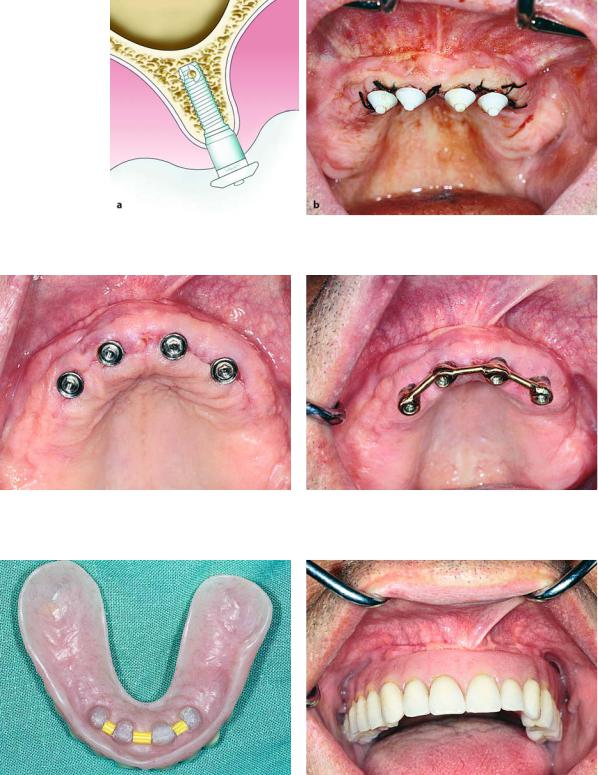
Then 15–20 days after placement of the abutments, the patient is ready to begin the procedure for a fixed or mobile prosthetic restoration (Fig. 15.19). A bar may be fabricated joined to the implants with screws, and an overdenture may be adapted to the bar with the aid of clips (Figs. 15.20–15.22).
Chapter 15 Osseointegrated Implants |
345 |
Fig. 15.18 a, b. Healing caps placed on abutments of implants.
Fig. 15.19. Clinical photograph showing abutments immediately after removal of sutures
a Diagrammatic illustration. b Clinical photograph
Fig. 15.20. Implants joined by overdenture bar over which prosthetic restoration is to be placed
Fig. 15.21. Clips in denture which snap onto bar for retention and support of denture
Fig. 15.22. Clinical photograph showing prosthetic restoration adapted to implants