

Text 8 grinding machines
There are following types of grinding machines: standard universal as well as plain cylindrical grinders for work sizes up to 1500 mm; centreless grinding machines for work sizes from 3 to 150 mm; copy-grinders, tool-sharping machines, etc.
Brief specifications of some cylindrical grinder models are given below.
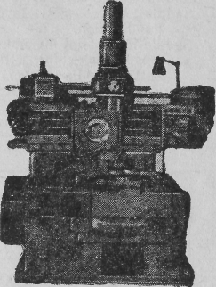
Vertical drilling machine, model 2170
|
|
Model designation | |||||
|
3150 |
3153M |
3164 |
3172 |
3174 |
ХIII-94 | |
|
Maximum workplace diameter, mm
Distance between centres, mm
Weight of machine, t |
100
300
1.1 |
130
500
2.1 |
400
2000
10 |
560
4000
30 |
800
5000
40 |
1500
7500
80 |
Text 9 gear shaper model 5m14
The model 5M14 Gear Shaper is designed for cutting external and internal spur gears.
Model 5M14 gear shapers are extensively used in the automobile, tractor, and machine-tool industries, especially for gears with teeth up close to a shoulder and with only a slight clearance recess, as well as for other industries in which the cutting of spur gear is required.
 CERTIFICATE
Manufacturing Works
Model 5M14
Work's serial No.____________,
years of manufacture ___________
Purpose — for cutting spur gears
Overall dimensions:
Floor space, mm 1800x1350
Height, mm 2200
Net weight, kg 3450
SPECIFICATIONS
Capacity
Maximum diameter of gears accommodated, mm 500
Maximum face width of gears cut, mm 105
Maximum module of gears cut (for steel), mm 6
Stroke of cutter spindle, mm:
maximum 125
minimum 0
Maximum outside diameter of internal gears accommodated, mm 550
Minimum pitch diameter of cutter, mm 100
Maximum automatic withdrawal of cutter at the end of operating cycle,
mm 18
Distance from work-spindle flange to cutter locating surface, mm:
maximum 170
minimum 45
Saddle maximum travel, mm 500
Saddle travel per revolution of the crank handle, mm 3
Saddle travel dial divisions, mm 0.02
Scale with index for setting up and checking the cutter-spindle stroke available
Work-table fast-rotation for truing the work available
Work clamping manual
Maximum work withdrawal from cutter during return stroke (relieving
motion), mm 0.5
Main drive mechanism
|
Speed step |
Setting up main drive mechanism |
Stepped speed variation | |||
|
Lever position |
Cutter strokes per minute |
Available power on cutter spindle, kW |
Weakest link in main drive gear train | ||
|
at rated power of drive motor |
permitted by weakest link | ||||
|
0 |
|
Neutral |
|
|
|
|
1 |
125 |
|
|
| |
|
2 |
179 |
|
|
| |
|
3 |
265 |
|
|
| |
|
4 |
400 |
|
|
| |

Feed mechanism
Rotary feeds
|
L
1, 3 – engaged; 2 – disengaged; 4 – reversing lever; 5 – square shank for rotating cutter and blank by hand |
Feed step |
Change gear notation |
Number of cutter strokes per cutter revolution |
Rotary feed, mm, per cutter revolution along pitch circle of 100 mm cutter | |
|
a — driver gear b — driven gear | |||||
|
Number of teeth | |||||
|
a |
b | ||||
|
1 |
58 |
31 |
628 |
0.51 | |
|
2 |
55 |
34 |
729 |
0.44 | |
|
3 |
50 |
39 |
897 |
0.35 | |
|
4 |
47 |
42 |
1028 |
0.3 | |
|
5 |
42 |
47 |
1287 |
0.24 | |
|
6 |
39 |
50 |
1475 |
0.21 | |
|
7 |
34 |
55 |
1850 |
0.17 | |
 evers
for setting the rotary feed mechanism:
evers
for setting the rotary feed mechanism:Setting-up formula
![]() with a cutter diameter dc
= 100 mm
the formula will be
with a cutter diameter dc
= 100 mm
the formula will be ![]() 3.66×S
3.66×S
S – rotary feed
especially for gears with teeth up close to a shoulder and with only a slight clearance recess – особенно при нарезке закрытых венцов и тонких зазоров выемок