reading / British practice / Vol D - 1990 (ocr) ELECTRICAL SYSTEM & EQUIPMENT
.pdfElectrical system monitoring and interlocking schemes
SOURCE 1
1 , 0V DC SUPPLY
SECTION A |
SECTION B |
|
|
|
CB1 LOC |
|
|
|
|
|
|
|
|
|
|
|
CB2 POE |
||
- -a |
|
(re-1.."•-wip |
|
||
|
|
||||
ICB2 LOC
CB 3 POS
-0--* (4■1%.-ms
CR3 LOG
CB4 POS
a-
|
|
|
CB4 LOC |
|
|
|
|
|
|
|
|
|
|
|
|
|
|
|
|
|
|
|
|
|
a |
|
|
|
|
|
|
|
|
|
|
|
||
|
|
|
|
|
|
|
|
|
OBI |
|||
|
1 R-1 |
|
|
|
|
|
|
|
||||
|
|
|
|
|
|
|
|
|
|
|
a |
|
|
|
|
|
|
|
|
|
|
|
|
|
|
|
4P-1 |
|
|
|
|
|
|
|
|
|
|
a |
|
|
|
|
|
|
|
|
|
|
|
|
|
|
|
|
|
|
|
|
|
|
|
|
||
|
|
|
I R 2 |
4R.2 |
|
|
|
CB2 |
||||
2R , |
|
3R.I |
|
|
|
|
|
|
|
|||
|
|
|
|
|
|
|
||||||
|
|
|
|
|
|
|
|
|
|
|
|
|
|
|
|
|
|
|
PLANT |
|
|
|
|
||
|
|
|
|
|
|
PROTECT:ON < |
|
|
|
|
|
|
|
|
|
|
|
|
INTERLOCKS |
|
|
|
|
|
|
|
|
|
|
|
|
|
|
|
|
|
|
|
|
|
|
|
|
|
|
|
|
CB3 |
a |
||
|
|
|
|
|
|
|
|
|
|
|
|
|
|
|
|
|
|
|
|
|
|
|
|
|
|
|
|
|
|
SUPPLY a |
|
|
|
|
|
|
|
|
|
|
|
|
FAIL |
|
|
1\ |
CB4 |
|
|||
|
|
|
|
ALARM |
|
|
|
|
|
|
||
|
|
|
|
|
|
|
|
|
|
|||
FIG. 1.47 Circuit diagram showing '3 out of 4' interlocked circuit-breakers
SOURCE 2
SW.TC:HBO4 PD
SECTION C
:RC I
IRC 2
a |
---- |
|
IRC 3
iRC.4
a
already closed. Check synchronising interlock facilities are fitted to the LV circuit-breaker which prevents it closing if unacceptable voltage mismatch or phase differences exist.
Interconnectors, especially cable interconnectors, when not in service are usually left energised, from one end only, so as to monitor the integrity of the circuit continually. Bringing the interconnector into service, however, must always be accomplished via the circuit-breaker fitted with the check synchronising facilities.
To ensure that this procedure is always followed, operational electrical interlocks are fitted which prevent the circuit-breaker without synchronising facilities being closed if the circuit-breaker with the check synchronising is already closed. Check synchronising interlock facilities operate as described above.
The circuit and loop diagrams for the transformer or interconnector arrangement are shown in Figs 1.48 and 1.52 respectively.
When the above interlock scheme has to operate between local and remote circuit-breakers of such separation that direct wiring between the plant protection interlocks would cause excessive volt drop in the circuit-breakers control circuits, then circuitbreaker repeat relays are used.
•One out of two Operational electrical interlocks are fitted to the circuit-breakers of both feeder circuits connected to the board. These interlocks prevent both feeder circuit-breakers being closed at the same time, which would otherwise result in unacceptable paralleling of the supplies. Either of the two feeders may be selected for duty and closed onto the board, but having accomplished this the interlocks then prevent the remaining feeder circuit-breaker being closed. No synchronising facilities are required as the above interlock prevents the two supplies being connected together. This scheme is shown in Figs 1 .53 and 1.54..
•Two out of three This interlock scheme is designed to prevent the paralleling of supplies without in-
73

Electrical system design |
Chapter 1 |
|
|
|
|
|
|
11kV. 3 3kV AND 415V |
BOARD |
|
BOARD 2 |
|
|
|
(1) |
(.1) |
|
2
y],
INTERCONNECTOR
..--■•■••••■■ HV
r•-•
\
1 , 3 301 TRANSFORI,IER
TRANSFORMER
|
|
|
|
|
|
LV |
|
|
|
|
|
|
|
|
|
|
|
|
|
|
LOC |
|
|
|
|
|
|
|
|
|
|
||||
|
|
|
|
|
|
|
|
|
|
|
|
|
|
|
|||
|
|
|
|
|
|
|
|
|
|
|
DIRECTLY CONNECTED INTERLOCKS |
|
|
||||
|
|
|
|
|
|
|
|
|
|
|
— |
|
|
||||
|
|
|
CA |
|
|
|
|
|
|
|
|
|
OPPOSITE END C8 2 OR |
|
|
||
|
|
Ca |
|
|
|
|
|
|
|
|
|
CB HV PLANT PROTECTiON |
|
|
|||
|
|
OE LV |
|
|
|
|
|
|
|
|
|
INTERLOCKS |
|
|
|||
|
|
|
|
|
|
|
|
|
INTERLOCKS VIA RELAY WHERE ROUTE LENGTH |
|
|
||||||
|
|
|
P05 |
|
|
|
BETWEEN SWITCHBOARDS INTRODUCES UNACCEPTABLE |
||||||||||
|
|
|
|
|
|
VOLT DROP |
|
|
|||||||||
|
|
CB |
OP |
|
|
|
|
|
|
|
|
|
|
|
|
|
J1 |
|
|
|
|
|
|
|
|
|
|
|
|
|
|
|
|||
|
|
|
|
|
|
|
|
|
|
|
|
|
|
|
|||
|
|
|
|
|
|
|
|
|
|
|
|
|
|
|
|||
|
|
05 |
LV |
|
|
|
|
1I} |
|
|
|
|
--C1=-0 |
||||
|
|
|
|
|
|
|
|
|
|||||||||
|
|
|
|
|
|
|
|
|
|
|
|
||||||
|
|
|
|
|
|
|
|
|
|
|
|
|
|
_ ARA |
|
J2 |
|
|
|
|
PR A |
1 |
|
|
|
|
|
|
|
|
|
I |
|
||
|
|
|
|
0 |
|
|
|
|
|
|
|
|
|
||||
|
|
|
|
|
|
|
|
|
–W-'--- |
|
|
||||||
|
|
|
..? |
|
|
|
|
|
|
|
|
OPPOSITE END CB 2 OA |
|
|
|||
|
|
|
|
|
|
|
|
|
|
|
|
CB NV PLANT PROTECTION |
|
|
|||
|
|
|
|
|
|
|
|
|
|
|
--INTERLOCKS |
|
|
||||
|
|
|
|
|
|
-- |
|
|
|
"– rt |
|
|
|||||
FIG. 1.48 Circuit diagram showing cabled interconnector and transformer electrical interlock
hibiting the operational flexibility of the system. Operational interlocks are fitted to the circuit-breakers of both feeder circuits and on the bus section circuitbreaker of the board. The system may be operated with both feeders closed onto their respective halves of the board (as long as the bus section circuitbreaker is open), or if maintenance is to be carried out on one of the feeder circuits, both halves of the board can be coupled together via the bus section circuit-breaker and the board fed from the remaining feeder. No synchronising facilities are required as the interlock prevents any paralleling of supplies. This scheme is shown in Figs 1.55 and 1.56.
• Sequence operational interlocks Sequence interlocks, if required, are to ensure the closure of switch-
gear in a correct and predetermined sequence with all out-of-sequence operations inhibited.
If sequence interlocks are specified on the transformer and interconnector circuits, their application must be developed and incorporated into the operational interlocking scheme as shown in Fig 1.57. It should be noted that the sequence interlock does not inhibit the operation of circuit-breaker No 2 in any way, and it is not therefore an alternative to an operational interlock.
8.4 Computer-based systems
As mentioned above, an alternative and more flexible arrangement for system monitoring is to utilise a computer-based scheme. The most recent of these installed by the CEGB has been at Heysham 2. From the description of the electrical auxiliaries system in Section 3.2 of this chapter, it will be apparent that a relay logic scheme for achieving interlocking could have proved to be cumbersome and possibly restrictive in the connections available to the operators. The decision was therefore made to develop and install a computer-based monitoring system. The block diagram for a computer-based fault level monitoring and indication equipment which has been installed is shown in Fig 1.58.
This equipment does not prevent any circuit-breaker from closing. The equipment advises the operator when it is unsafe to close a circuit-breaker by an indication at the point of switchgear control. Dual computer systems operating in a main and standby mode are provided for main unit failure or routine maintenance. The equipment is designed for mean time between failure (MTBF) of 10 years. The computer system allows changes to be made to the number of circuitbreakers being monitored and the plant data used in the computer model without the need to modify the software.
The fault level calculation and graphical display software for the system is based on the UMIST IPSA package (see Chapter 2) with modifications to enable the software to run in real-time, providing colour displays acceptable for use in a central control room (CCR) and switchgear safety status information (LED states).
As the software has been specified to be flexible and allow circuits and switchboards to be added arid removed, it follows that it can be used on future or existing power stations.
A monitor in the CCR can display the connections and switchgear for any of the switchboards included in the system. The display identifies any switchgear which cannot be closed safely at any instant in time and gives the potential increase in fault level if this were to be done. Each switchgear control switch in the CCR is also provided with a red LED, which is illuminated if it is unsafe to close the circuit. A times
74

|
|
|
|
|
|
|
|
|
|
Electrical system monitoring and interlocking schemes |
||
|
|
|
|
|
|
|
|
|
|
|
|
|
|
|
|
|
|
|
|
|
|
|
|
|
|
|
|
|
|
|
|
|
|
|
|
|
|
|
|
|
|
|
|
New Symbol |
|
Component description |
|
||||
|
|
Old Symbol |
|
|
||||||||
|
|
|
|
|
|
|
|
|
|
|||
|
|
|
|
|
|
|
|
|
|
|
|
|
|
|
|
|
|
|
|
( k |
|
Withdrawable metelcled switch9ear |
|
||
|
|
|
|
|
|
|
|
|
||||
|
|
|
|
|
|
|
|
|
|
|
|
|
|
|
- 7 |
|
|
)1 |
|
Circuit-breaker general symbol |
|
||||
|
|
|
|
|
|
|
Y |
|
|
|
||
|
|
|
|
|
|
|
(0, -) |
|
|
|
||
|
|
|
|
|
|
|
|
|
|
|
Circuit-breaker with HBC tripping use |
|
|
|
|
|
|
|
|
|
|
|
|
|
|
|
|
|
|
|
|
|
|
i |
|
|
|
|
|
|
|
|
|
|
|
|
|
I |
|
Ott-load Disconnector |
|
|
|
|
|
T |
|
|
|
|
|
|
||
|
|
|
|
|
|
|
|
|
|
|
||
|
|
|
|
|
|
Y |
|
|
|
|||
|
|
|
|
|
|
|
|
|
|
|
Fuses: (LH) general symbol |
|
|
|
|
|
|
II |
I |
|
|
I/ |
|
(RH) with supply side shown by thick line |
|
|
|
|
|
|
|
|
|
|
|
|||
|
|
|
|
|
|
|
_ |
|
|
|
||
|
|
|
|
|
|
|
— |
|
Relay coil |
|
||
|
|
|
|
|
|
|
— |
|
|
|
||
|
|
|
|
|
|
|
|
|
|
|
|
|
|
|
—10 OH |
|
|
|
|
|
|
Relay Contact: normally closed in de-energised stale |
|
||
|
|
|
|
|
|
|
|
|
||||
|
|
|
—0 0— |
|
|
|
|
|
|
Relay Contact: normally open in de-energised state |
|
|
|
|
|
|
|
|
|
|
|
|
|
||
|
|
|
|
|
|
|
|
|
|
|
|
|
|
|
|
|
|
Fic. 1.49 Index of component symbols, old and new |
|||||||
record is also provided for each switchgear change of state, for confirmation of operation and post-incident analysis.
The information provided by the computer will be used as an advisory aid by the operator. Although a computerised interlocking system has been installed at the Drax coal-fired power station, it was decided not to provide full interlocking at the Heysham 2 nuclear power station. This decision was taken so that the operators would not be inhibited from reestablishing vital electrical supplies under controlled emergency conditions to ensure reactor safety.
The natural progression of the computer-based systems is towards full interlocking schemes and elec-
trical auxiliaries system remote control. The CEGB are investigating several options to this end which, in the case of the remote control feature, would supersede the need for the full mimic panel in the CCR with discrepancy switch control used at present.
8.5 Maintenance interlocking equipment
Maintenance interlocking is concerned essentially with personnel safety while maintenance is being performed on electrical equipment. Plant damage must also be considered, but is less likely due to the plant being nonoperational during maintenance.
75

Electrical system design |
Chapter 1 |
|
|
Li. El ,i--./1
5
I Or, /
4 V
A
Indicates electrical interlocks between a circuitbreaker group.
The figure in the LH corner denotes the total number of circuit-breakers in the group permitted to be closed
at any one time The figure in the RH corner denotes the total number of breakers in the group.
Indicates electrical interlocks between a circuitbreaker group.
The figure in the LH corner denotes that a maximum of 3 out of the 5 circuit-breakers with this symbol may be closed at any one time. The exception to this would
be when a selected circuit-breaker is open. i.e.. the bus section, under this condition the interlock allows
the remaining 4 breakers to be closed.
Transformer electrical interlock.
This circuit-breaker, (HV) can only be closed if the remote circuit-breaker, (LV) is open_
Interconnector electrical interlock.
This circuit-breaker can only be closed if the remote circuit-breaker is open.
Synchronising.
Circuit-breaker fitted with synchronising facilities, Can only be closed if supplies are synchronised.
Automatic synchrbnising
Circuit-breaker fitted with auto-synchronising facilities. Once this function has been selected the
breaker will auto close when supplies are synchronised
E / |
Transtormer electrical interlock. |
|
This circuit-breaker (LV) can only be closed if the |
||
y |
||
remote circuit breaker (HV) is closed, and supplies |
||
|
are synchronised. |
interconnector electrical interlock.
This circuit-breaker can only be closed if the remote
circuit breaker is closed, and supplies are synchronised.
FIG. 1.50 Definition of symbols for types of interlock
Although the CEGB Safety Rules do not require mechanical interlocking, it is current policy to provide a system of coded-key interlocks to assist the operator in applying the Safety Rule requirements. The interlocking system is based on the following sequence:
•Isolation at all points of supply.
•Proof of isolation.
•Earthing all items of equipment.
•Proof of earthing.
•Issue of Permit for Work'.
The objective is to allow safe access to electrical equipment for maintenance purposes. Access is controlled by a rigid set of Safety Rules specifically drawn up and controlled by the CEGB, under a formal Permit for Work' system. These ensure that access is denied until all electrical apparatus has been switched off,
isolated and in the case of HV, earthed. To assist the operators in implementing the Safety Rules it is normal to apply a discrete coded-key procedure designed for each system. This procedure only allows access to the next stage, after the previous operation has released a coded-key which in turn has to satisfy the next set of criteria. Following the system ensures that all the necessary isolation and earthing has been achieved in accordance with the Safety Rules prior to allowing man access to plant.
The choice of a maintenance interlocking scheme is largely dependent on the perceived maintenance requirement and complexity of the plant concerned. The mechanical interlocking will be based on codedkeys and key exchange boxes.
The following type of mechanical interlock key facilities are available to be used:
Symbol Type
D A
Function
Proof of earthing key
•A key free only when the circuitbreaker or earthing switch or switching device where applicable is closed in either the busbar or circuit side earthing location. Removal of the key shall lock the circuit-breaker or earthing switch or switching device in the earthing location. (Key type 'Al'
—circuit earthing, Type 'AT
—busbar earthing.)
Note: Although 3.3 kV circuitbreakers are provided with circuit earthing and, where specified, busbar earthing facilities; 3.3 kV fused switching devices are provided with facilities for circuit earthing only.
•Alternatively, a key made available by an Authorised Person after the satisfactory application of portable earths.
BPermissive close key
A key which, when inserted, permits the circuit-breaker or switching device to be closed and is free only when the circuit-breaker or switching device is open. Attempted removal of the key when the circuitbreaker or switching device is closed shall not cause tripping of the circuit-breaker or switching device. Alternatively for a disconnector, a
76

Electrical system monitoring and interlocking schemes
, .I.I. 7..... HV
HV
|
|
|
|
|
|
|
|
|
|
|
|
|
|
|
|
|
|
|
|
|
|
|
|
|
|
|
|
|
|
|
|
|
|
|
|
|
|
|
|
|
|
|
|
|
|
|
|
|
|
|
|
|
|
|
|
|
|
|
|
|
|
|
|
|
|
|
|
|
, |
|
|
|
|
|
|
|
|
|
|
|
|
|
|
|
|
|
|
|
|
|
|
|
|
|
i |
|
|
|
|
|
|
|
|
|
|
|
|
|
|
|
|
|
|
|
|
|
|
|
|
|
|
|
|
|
|
|
|
|
|
|
, |
|
|
|
|
, |
|
|
|
|
|
|
|
|
|
|
|
|
|
|
|
|
|
|
|
|
|
|
|
I |
|
|
|
|
|
|
|
|
|
|
|
|
|
|
|
|
|
|
|
|
|
|
|
|
|
|
|
|
|
|
|
|
|
|
|
I |
|||||||
|
|
|
|
|
|
|
|
|
|
|
|
|
|
|
|
|
|
|
|
|
|
|
|
|
|
|
|
|
|
|
|
|
|
|
|
|
|
|
|
|
|
|
|
|
|
|
|
|
|
|
|
|
|
1 |
|
|
|
|
|
|
|
||||||
|
|
|
|
|
|
|
|
|
|
|
|
|
|
|
|
|
|
|
|
|
|
|
|
|
|
|
1 |
|
|
|
|
|
|
|
|
|
|
|
|
|
|
|
|
|
|
|
|
|
|
|
|
|
|
|
|
|
|
|
|
|
|
|
I |
||||
|
|
|
|
|
|
|
|
|
|
|
|
|
|
|
|
|
|
|
|
|
|
|
|
|
|
|
|
|
|
|
|
|
|
|
|
|
|
|
|
|
|
|
|
|
|
|
|
|
|
|
|
|
|
|
I |
|
|
|
|
||||||||
|
|
|
|
|
|
|
|
|
|
|
|
|
|
|
|
|
|
|
|
|
|
|
|
|
|
|
|
|
|
|
|
|
|
|
|
|
|
|
|
|
|
|
|
|
|
|
|
|
|
|
|
|
|
|
|
|
|
|
|
|
|
|
|
||||
X |
|
|
ill |
|
|
|
|
|
|
|
|
|
|
|
|
|
|
|
1 |
-.- ji |
(11 |
|
|
|
|
|
|
|
|
|
(11 |
|
|
|
|
|
|
|
|
|
|
|
|
|
|
|
|
|
|
|
|
||||||||||||||||
|
|
|
|
|
|
|
|
|
|
|
|
|
|
|
|
|
|
|
|
|
|
|
|
|
|
|
|
|
|
|
|
jz _ |
|
|
|
|
|
|
|
|
|
|
|
|
|
|
|
|
|
|
|
|
|
...- |
|
|
|
|
|
|
|
|
|
|
|
||
|
|
|
|
|
|
|
|
|
|
|
|
|
|
|
|
|
|
|
|
|
|
|
|
|
' ,1i |
|
|
|
EA |
|
|
|
|
|
|
|
|
|
|
|
|
|
|
|
|
|
|
|
S |
|
|
|
|
|
|
|
|
||||||||||
|
|
|
I |
|
|
)2 1 |
|
|
|
|
|
|
|
|
|
|
|
|
|
|
4 |
|
|
|
5 IIL 1 |
\ |
|
|
|
|
|
|
|
|
|
|
|
|
|
|
|
|
|
|
|
|
|
|
|
|
|
|
|
|
|
|
|
||||||||||
|
|
|
|
|
|
|
|
|
|
|
|
|
|
Y |
|
|
|
|
|
|
|
|
|
|
|
|
|
|
|
|
|
|
|
|
|
|
|
|
|
|
|
|
|
|
|
|
|||||||||||||||||||||
• ._. t.., |
|
.... |
|
|
. |
|
|
|
|
|
|
|
|
|
|
|
|
|
|
|
|
|
, |
|
|
|
Y 1 . |
|
|
|
|
|
|
|
|
|
Y |
|
|
|
|
|
|
|
|
|
|
|
|
|
|
|
|
L v |
|
|
|
||||||||||
|
|
|
I BOARD' |
|
|
|
|
|
|
|
|
|
|
|
|
|
|
|
|
|
BOARD? |
|
|
|
|
|
1 |
|
|
|
|
|
|
|
|
|
|
|
|
|
|
BOARD 3 |
1 |
|
|
|
|
|
|
|
|
|
|
|
|
||||||||||||
|
|
, - - - - - - - - - - - - - - - - - - - - - - - - - |
|
|
|
|
|
|
|
|
|
|
|
|
|
|
|
_1 - - - - - - - - - - - - - - - - - - - - - - - - - - - - - - - - - - - - - - - |
J |
|
|
|
|
|
|
|
|
|
|
|
|
||||||||||||||||||||||||||||||||||||
|
|
|
|
|
|
|
|
|
|
|
|
|
|
|
|
|
|
|
|
|
|
z IkV 3 3IN d. 415 'V |
|
|
|
|
|
|
|
|
|
|
|
|
|
|
|
|
|
|
|
|
■onLme. |
||||||||||||||||||||||||
|
|
|
|
|
|
|
|
|
|
|
|
|
|
|
|
|
|
|
|
|
|
|
|
|
|
|
|
|
|
|
|
|
|
|
|
|
|
|
|
|
|
|
|
|
|
|
|
|
|
|
|
|
|
|
|
||||||||||||
|
|
|
|
|
|
|
|
|
|
|
|
|
|
|
|
|
|
|
|
|
|
|
|
|
|
|
|
|
|
|
|
|
|
|
|
|
|
|
|
|
|
|
|
|
|
|
|
|
|
|
|
|
|
|
|
|
|
|
|
|
|
|
1 /kV |
3 3■0., a 4'5V LV |
|||
|
|
|
|
|
|
|
|
|
|
|
|
|
|
|
|
|
|
|
|
|
|
|
|
|
|
|
|
|
|
|
|
|
|
|
|
|
|
|
|
|
|
|
|
|
|
|
|
|
|
|
|
|
|
|
|
|
|
|
|
|
|
|
|
|
|
||
SOURCE ' |
|
z_ _ _ |
|
|
|
|
|
|
|
|
|
|
|
|
|
|
SOURCE? |
|
|
|
|
|
|
|
|
|
|
|
|
|
|
|
|
|
|
|
|
|
|
|
|
|
|
|
|
|
|
|
|
|
|
|
|
|
I 11,V 3 3kv 8 415V |
||||||||||||
|
|
|
|
|
|
|
|
|
|
|
|
|
|
|
|
|
|
|
|
|
|
|
|
|
|
|
|
|
|
|
|
|
|
|
|
|
|
|
|
|
|
|
|
|
|
|
|
|
|
|
|
|
|
|
|
|
|
|
|||||||||
|
|
|
|
|
|
|
|
|
|
|
|
|
|
|
|
|
|
|
|
|
|
|
|
|
|
|
|
|
|
|
|
|
|
|
|
|
|
|
|
|
|
|
|
|
|
|
|
|
|
|
|
|
|
|
|
|
|
|
|
|
|
|
|
|
|||
|
|
|
|
|
|
|
|
|
|
|
|
|
|
|
|
|
|
|
— |
|
|
|
|
SOURCES1 |
2 |
|
|
|
|
|
il |
|
|
|
|
|
|
|
|
|
|
|
|
|
|
|
80ARD 1 |
|
BOARD? |
||||||||||||||||||
|
|
|
|
|
|
|
|
|
|
|
|
|
|
|
|
|
|
|
|
|
|
|
|
|
|
|
|
|
|
|
|
|
|
|
|
|
|
|
|
|
|
|
|
||||||||||||||||||||||||
|
|
|
|
|
|
|
|
|
|
|
|
|
|
|
|
|
|
|
|
|
|
|
|
|
el \ |
|
|
|
rt |
|
|
|
|
|
|
|
|
|
|
|
|
|
|
|
|
|
|
|
|
||||||||||||||||||
|
|
|
|
i |
|
|
|
|
|
|
|
|
|
|
|
|
|
|
|
|
\ II) |
|
|
|
|
|
|
|
|
|
|
|
|
|
|
|
|
|
|
|
|
|
|
|
|
|
|
|
|
|
|
|
|
|
|
|
|
|
|
||||||||
|
|
|
|
|
|
|
|
|
|
|
|
|
|
|
|
|
|
|
|
|
|
|
|
|
|
|
|
|
|
|
|
|
|
|
|
|
|
'.. |
1 |
|
|
=" |
|
|
|
|
|
|
|
|
|||||||||||||||||
|
|
|
|
|
|
|
|
|
|
|
|
|
|
|
|
|
|
|
|
|
|
|
|
|
|
|
|
|
|
|
|
|
|
|
|
|
|
|
|
|
|
|
|
|
|
|
|
|
|
|
|
|
|
|
|||||||||||||
|
|
|
|
|
|
|
|
|
|
|
|
|
|
|
|
|
|
|
|
|
|
|
|
|
|
|
|
|
|
|
|
|
|
|
|
|
|
|
|
|
|
|
|
|
|
|
|
|
|
|
|
|
|
|
|
|
|
|
|
|
|
|
|||||
• |
|
|
|
|
|
|
|
|
|
|
|
|
|
|
|
|
|
|
|
|
|
|
|
|
|
|
|
|
—/ |
|
|
' |
|
|
|
|
|
|
|
|
|
|
|
|
|
|
|
|
|
|
|
|
|
|
|
|
|
— \I-I |
|||||||||
|
|
|
|
|
|
|
|
|
1 |
|
|
|
|
|
|
|
|
|
|
|
|
|
|
|
|
|
|
|
|
|
|
|
|
|
|
|
|
|
|
|
|
|
|
|
|
|
|
) S |
|
||||||||||||||||||
|
|
|
|
|
|
|
|
|
|
|
|
|
|
) |
|
|
|
|
|
|
|
|
|
|
|
|
|
|
|
|
I |
|
|
|
|
|
|
|
|
|
|
|
|
|
|
|
2 |
||||||||||||||||||||
|
|
|
|
|
|
|
|
|
|
|
|
|
|
l1 |
|
|
|
|
|
|
|
|
|
|
|
|
|
|
|
|
|
|
|
|
|
|
|
|
|
|
|
|
|
|
|
|
|
|
|
||||||||||||||||||
|
\:11('' |
|
|
|
|
|
|
|
|
|
|
|
|
|
|
|
|
|
|
|
"ii |
|
|
|
Y |
|
|
! |
|
I |
|
|
|
|
|
|
|
|
|
|
|
|
|
|
Y |
|
|
|
Y |
||||||||||||||||||
■L■ |
|
-4(' |
— |
|
|
|
|
|
|
‘ SwITCHBOARD |
|
|
|
|
|
|
|
|
|
LI) |
|
|
kri |
|
|
|
|
||||||||||||||||||||||||||||||||||||||||
C |
>n< |
|
|
- |
— |
|
|
|
|
|
|
|
|
|
C--k-s--) |
|
|
|
|
|
|
|
|
||||||||||||||||||||||||||||||||||||||||||||
5E: |
- |
|
|
|
,,,../7 |
|
|
‘ |
|
|
|
|
|
|
|
|
|
|
|
|
|
|
|
|
|
|
|
|
|
|
|
|
|
|
|
|
|
|
|
|
|
||||||||||||||||||||||||||
|
CN A |
|
|
|
SECTION B |
|
...-- 7 |
|
|
SECTION C |
|
|
|
|
|
|
|
|
|
|
|
|
|
|
|
|
|
|
|
|
|
|
|
|
|
|
|
|
|
I NTERCONNECTOR |
|||||||||||||||||||||||||||
|
|
|
|
|
|
11.v 3 3kv 8 415v |
|
|
|
|
|
|
|
|
|
|
|
|
|
|
|
|
|
ilkV 3 3l0/ 8 41SV |
|
|
|
|
|
|
|
|
|
|
|
|
|
|
|
|
|
|
|
|
|
|
|
|
|
|
|||||||||||||||||
|
|
|
|
|
|
|
|
|
|
|
|
|
|
|
|
|
|
|
|
|
|
|
|
|
|
|
|
|
|
|
|
|
|
|
|
|
|
|
|
|
|
|
|
|
|
|
|
|
|
|
|
|
|
|
|
|
|
|
|
|
|
|
|
|
|||
|
|
|
|
|
|
|
|
|
|
|
\\EZ |
|
|
|
|
|
|
|
|
|
|
|
|
|
|
|
|
\E/l |
|
|
|
|
|
|
|
|
|
|
|
|
|
|
|
|
|
|
|
|
|
|
|
“kV33kv 8 415%! |
|||||||||||||||
SOURCE ' |
r |
|
|
|
|
|
|
|
|
|
|
|
|
SOURCE 2 |
|
|
|
|
|
|
|
|
|
|
|
|
|
|
|
SOURCE 3 |
|
|
|
|
|
|
|
|
|
|
|
|
|
|
|
|
|
|
|
|
|||||||||||||||||
|
|
i |
|
,r |
/ |
|
2 |
|
|
3 |
|
|
|
|
|
1 // |
|
|
|
|
|
2 |
|
3 |
\ |
|
|
|
|
\ \ |
|
|
|
|
|
|
|
|
|
|
|
SOURCE 1 |
|
|
|
|
|
|
|
|
|
|
|
|
|||||||||||||
|
|
1 |
|
|
|
|
|
|
|
|
|
|
|
|
|
|
|
|
|
|
|
|
|
|
|
|
|
|
|
|
|
|
|
|
|
|
|
|
|
|
V |
SOURCE 2 |
|||||||||||||||||||||||||
|
|
|
|
|
|
|
|
|
|
|
|
|
|
|
|
|
|
|
|
|
|
|
|
|
|
|
|
|
|
|
|
|
|
|
|
|
|
|
|
||||||||||||||||||||||||||||
|
A |
|
|
(I-,, |
|
|
|
|
|
|
|
|
|
|
|
A |
|
|
|
|
|
A |
|
|
|
|
|
|
|
, (I) |
|
|
|
\ |
|
|
|
|
|
|
|
|
|
|
ri't |
|
|
|
|
|
|
/I) |
|||||||||||||||
|
|
|
|
|
|
|
|
|
|
|
|
|
|
|
|
|
|
|
|
|
|
|
|
|
|
|
|
|
\ |
|
|
|
|
|
|
|
|
|
|
|
2 |
|
3 |
||||||||||||||||||||||||
|
|
|
|
|
|
|
|
|
|
|
|
|
|
|
|
|
|
|
|
|
|
|
|
|
|
|
|
|
|
|
|
|
|
|
|
|
|
|
|
|
|
|
|
|
|
|
|
|
|
|
|
|
|
|
|
|
|
|
|
|
|
|
|
|
|
||
|
|
|
|
|
|
|
|
|
|
|
|
|
|
|
|
|
|
|
|
|
|
|
|
|
|
|
|
|
|
|
|
|
|
|
|
Ali |
|
|
|
|
\\I |
|
|
|
|
|
|
|
|
|
|
|
|
|
|
|
|
|
|
|
|
||||||
|
|
|
|
|
|
|
|
|
|
|
|
|
|
|
|
|
|
|
|
|
|
|
|
|
|
|
|
|
|
|
|
|
|
|
|
4 |
|
|
|
|
|
(5) |
|
|
|
|
|
|
|
|
|
|
|
|
|
|
|
|
|
|
3 |
||||||
|
|
|
|
|
|
|
|
|
|
|
|
|
|
|
|
|
|
|
|
|
|
|
|
|
|
|
|
|
|
|
|
|
|
|
|
|
|
|
|
|
|
|
|
|
|
|
|
|
|
|
|
|
|
|
|
|
|
|
|
|
|
|
|||||
|
|
|
|
|
|
|
|
|
|
|
|
|
|
|
|
|
|
|
|
|
|
|
|
|
|
|
|
|
|
|
|
|
|
|
|
|
|
|
|
|
|
|
|
|
|
|
|
)1 |
|
|
|
|
|
|
|
|
|
|
|
|
|
||||||
|
|
|
|
|
|
|
|
|
|
|
|
|
|
|
|
|
|
|
|
|
|
|
|
|
|
|
|
|
|
|
|
|
|
|
|
|
|
|
|
|
|
I |
|
Y |
|
|
|
|
|
|
|
|
|
|
|
|
|
|
|
) |
|
||||||
|
|
|
|
|
|
|
|
|
|
|
|
|
|
|
|
|
|
|
|
|
|
|
|
|
|
|
|
|
|
|
|
|
|
|
|
|
|
|
|
|
|
|
|
|
|
|
|
|
|
|
|
|
|
|
|
|
|
|
|
|
|
|
|
|
|||
, |
|
|
|
|
|
|
|
|
|
|
|
|
|
|
|
|
|
|
|
|
|
|
|
|
|
|
|
|
|
|
|
|
|
|
|
|
|
|
|
|
|
! |
|
|
|
|
|
|
|
|
—Y—c---F—D—[)- - |
||||||||||||||||
|
|
|
SWITCHBOARD A; |
|
|
|
|
|
|
|
|
|
|
|
|
|
|
SWIT |
H. ROB |
|
|
|
|
|
|
|
|
|
|
|
SWITcHBOARD I |
|
|
|
|
|
|
|
|
|
|
||||||||||||||||||||||||||
|
|
|
L |
|
|
.....L |
|
|
|
|
|
|
|
|
|
|
|
|
|
|
|
|
|
|
|
|
|
|
|
|
|
1 |
|
|
|
|
|
|
|
|
|
|
|
|
|
|
|
|
|
|
|
|
|
|
|
|
|
|
|
|
|
|
|
|
|||
|
|
|
|
|
|
|
|
|
|
|
|
|
|
|
|
|
|
|
|
|
|
|
|
|
|
|
|
|
|
|
|
|
|
|
|
|
|
|
|
|
|
|
|
|
|
|
|
|
|
|
|
|
|
|
|
|
|
|
|
|
|
|
|
||||
|
|
|
|
|
|
|
|
|
|
|
|
|
|
|
|
|
|
|
|
|
|
|
|
|
|
|
|
|
|
|
|
|
|
|
|
|
|
|
|
|
|
|
|
|
|
|
|
|
|
|
|
|
|
|
|
|
|
|
|
|
|
|
|
|
|
|
|
|
|
|
|
|
|
|
|
|
|
|
|
|
|
|
|
|
|
|
|
|
|
111,V |
3 3kV a 415V |
|
|
|
|
|
|
|
|
|
|
|
|
|
|
|
|
|
|
|
|
|
|
|
|
|
|
|
|
|
|
|
|
|
|
|
|
|
|
|
|
|
|
|
|
|
|
|
|
|
|
|
|
|
|
|
|
|
|
|
|
|
|
|
|
|
|
|
|
|
|
|
|
|
|
|
|
|
|
|
|
|
|
|
|
|
|
|
|
|
|
|
|
|
|
|
|
|
|
|
|
|
|
|
|
|
|
||||||
SCJRCE , |
|
|
|
|
|
|
|
|
|
SOURCE 2 |
|
|
|
SOURCE 1 |
|
|
|
|
|
SOURC E 2 |
|
|
|
|
|
|
|
SOURCE 3 |
|
|
|
|
|
SOURCE I |
|
SOURCE 2 |
|||||||||||||||||||||||||||||||
|
|
|
|
|
|
|
|
|
|
|
|
|
|
|
|
|
|
|
|
|
|
|
|
|
|
|
|
|
|
||||||||||||||||||||||||||||||||||||||
|
|
|
|
|
|
|
|
|
|
|
|
|
|
|
|
|
|
|
|
|
|
|
|
|
|
|
|
|
|
|
|
|
|
|
|
|
|
|
|
|
|
|
|
||||||||||||||||||||||||
|
|
|
|
|
|
|
|
|
|
|
|
|
|
|
|
|
|
|
|
|
|
|
|
|
|
|
|
|
|
|
|
|
|
|
|
|
|
|
|
|
|
|
|
|
|
|
|
|
|
|
|
(1) |
|
|
|
|
V3 |
|
i'll |
||||||||
|
|
|
|
|
|
|
|
|
|
|
|
|
|
|
|
|
|
|
|
|
|
|
|
|
|
|
|
|
|
|
|
|
|
|
|
|
|
|
|
|
N 1.3 |
|
|
|
|
|
|
|
|
|
|||||||||||||||||
|
:\I |
|
|
|
|
|
|
|
|
|
|
|
2'.31 |
|
|
|
|
\11 |
|
|
|
|
|
\ 2 |
|
|
|
|
|
|
|
|
|
|
|
|
|
|
|
|
|
|
|
|
|
I |
|
3 |
|
|
|
||||||||||||||||
|
|
|
|
|
|
|
|
|
|
|
|
|
|
|
|
|
|
I |
|
|
|
|
|
1 |
|
|
|
|
|
|
|
) |
|
|
|
|
|
|
|
|
|
|
|
|
|
|
|
|
|
|
|
|
|
|
|
||||||||||||
|
|
|
|
|
|
|
|
|
|
|
|
|
|
|
|
|
|
|
|
|
|
|
|
|
|
|
|
|
|
|
|
|
|
|
|
|
|
|
|
|
|
|
|
|
|
|
|
|
|
|
|
|
|
I |
|
|
|
|
|
||||||||
|
|
|
|
|
|
|
|
|
|
|
|
|
|
|
|
|
|
|
|
|
|
|
|
|
|
|
|
|
|
|
|
|
|
|
|
|
|
|
|
|
|
|
|
|
|
|
|
|
|
|
|
|
|
|
|
|
|
|
|
|
I |
|
|
|
|
|
|
|
|
|
|
|
"•L' 3 3,2 1415V |
|
|
|
|
|
|
|
|
|
|
|
|
,,,,„ „k,„&4,5, |
|
|
|
|
|
|
|
|
|
|
|
|
|
|
|
|
|
|
|
|
I' kV 3 3k 1V B JIEV |
|
|
|
|
||||||||||||||||||||||||
|
|
|
|
|
|
|
|
|
|
|
|
|
|
|
|
|
|
|
|
|
|
|
|
|
|
|
|
|
|
|
|
|
|
|
|
|
|
|
|
|
|
|
|
|
|
|
|
|
|
|
|
|
|
|
|
|
|
|
|
||||||||
|
|
|
|
|
|
|
|
|
|
|
|
|
|
|
|
|
|
|
|
|
|
|
|
|
|
|
|
|
|
|
|
|
|
|
|
|
|
|
|
|
|
|
|
|
|
|
|
|
|
|
|
|
|
|
|
|
|
|
|
|
|||||||
|
|
|
|
|
|
|
|
|
|
|
|
|
|
|
|
|
|
|
|
|
|
|
|
SOURCE I |
|
|
|
|
|
|
|
|
|
|
|
|
|
|
|
|
|
|
SOURCE? |
|
|
|
|
|
|
|
|
|
SOURCE 3 |
||||||||||||||
|
|
|
|
|
|
|
|
|
|
|
|
|
|
|
|
|
|
|
|
|
|
|
|
|
|
|
|
|
|
|
|
|
|
1 |
|
|
|
|
|
|
|
|
|
|
|
|
|
|
|
|
|
|
|
|
|
|
|
|
|
|
|
|
|
I |
|
|
|
|
|
|
|
|
|
|
|
|
FA |
|
|
|
|
|
|
|
|
|
|
(I) r |
— |
|
|
|
|
|
|
|
|
|
|
|
|
|
|
|
|
|
|
|
|
|
|
|
I |
|
|
|
|
|
|
|
|
|
|
|
|||||||||||
|
|
|
|
|
|
2 |
|
|
|
|
|
|
|
4 |
|
|
|
|
|
ril |
7 |
|
|
|
(11 |
|
|
|
|
|
|
|
|
|
|
|
|
|
|
|
|
|
|
|
|
|
( |
) |
|
||||||||||||||||||
|
|
|
|
|
|
|
|
|
|
|
|
|
|
|
|
|
|
|
|
i |
|
|
|
|
|
|
|
|
|
|
|
|
|
|
|
|
|
|
|
|
|
|
|
|
|
|
|
|
|
|
|||||||||||||||||
|
|
|
|
|
|
|
|
|
|
|
|
|
|
|
|
|
|
|
|
|
|
|
|
|
|
|
- - - - - - - - - - - - - - - - - - - - - - - - - - - - - - - - - - - - - - - - - - - - - - - - - - - - - - - - - - - - - |
|
|
|
|
|
|
|
|
|
|
|
|
|
|
|
|
|
|
|
|||||||||||||||||||||
|
|
|
t |
|
|
|
|
|
|
|
|
|
|
|
|
|
|
|
|
|
|
|
|
|
I--i |
|
|
|
|
\2Ir.- |
" |
|
|
|
|
|
|
|
|
|
|
|
|
to |
s |
|
|
|
|
re/7 |
k' 4 |
, d |
_ |
|
|||||||||||||
|
|
|
|
|
|
|
|
|
|
|
|
|
|
|
|
|
|
|
|
|
|
|
|
|
|
|
|
|
|
|
|
|
|
|
|
|
|
|
|
||||||||||||||||||||||||||||
|
|
|
|
|
|
|
|
|
|
|
|
|
|
|
|
|
1 |
|
|
|
|
II |
|
|
|
|
|
|
|
|
|
|
|
|
|
|
|
|
|
|
\,.) |
|
|
|
|
|
|
v \ |
|
) |
) |
|
|
||||||||||||||
|
|
.) — |
|
|
'i rE |
Y |
|
|
|
|
|
Y |
\'1 |
|
|
|
. 1 |
|
|
|
|
|
|
,....,, |
|
|
|
|
|
|
|
|
|
|
|
|
|
|
|
|
|
|
|
|
|
|
|
|
|
||||||||||||||||||
|
|
Y |
|
|
Y |
|
|
|
|
|
|
|
|
|
|
|
|
|
|
Y |
|
|
|
|
|
Y |
|
|
|
|
|
1 |
|
|
|
|
|
|
|
Y |
|
|
|
|
|
|
|
|
|
|
|
|
Y |
Y |
|||||||||||||
|
|
|
|
|
|
!I kV 3 3kV A 415V |
|
|
|
|
|
|
|
|
|
BOARD 1 |
|
|
|
|
|
|
|
|
|
|
|
|
|
|
BOARD ? |
|
1 skV 3 3101 6 4 4v |
|
BOARD 3 |
||||||||||||||||||||||||||||||||
|
|
|
|
|
|
|
|
|
|
|
|
|
|
|
|
|
|
|
|
|
|
|
|
|
|
|
|
|
|
|
|
|
|
|
|
|
|
|
|
|
|
|
|
|
|
|
|
|
|
|
|
|
|
|
|
|
|
|
|
|
|
|
|
|
|
|
|
FIG. 1.51 Index of basic operational interlock schemes
77

Electrical system design |
|
|
|
|
|
|
|
|
|
|
|
|
|
|
|
|
|
|
|
Chapter 1 |
||||||||||
|
|
|
|
|
|
|
|
|
|
|
|
|
|
|
|
|
|
|
|
|
|
|
|
|
|
|
|
|
|
|
|
|
|
|
|
|
|
|
|
|
|
MARSHALLING |
|
|
|
|
|
|
MARSHALL/NG I TERM INTERLOCKING |
|
I TERM I |
Ito vOLT DC |
|
||||||||
|
|
|
CB 1 OR CO LV |
|
|
|
|
|
|
CB2 OR CB HV |
|
|
|
|
||||||||||||||||
|
|
|
|
|
CUBICLE |
|
|
|
|
CUBICLE |
. No. |
RELAY PANEL |
|
. No . DISTRIBUTION BOARD |
|
|||||||||||||||
|
|
|
|
|
|
|
|
|
|
|
|
|
|
|
|
|
|
|
||||||||||||
|
|
|
|
|
|
|
|
|
|
|
|
|
|
|
|
|||||||||||||||
|
|
|
|
|
|
|
|
|
|
|
|
|
|
|
|
|
|
|
|
|
|
|
|
|
|
|
|
f |
|
|
|
|
|
POS |
|
|
|
|
|
|
|
|
|
|
|
|
|
|
|
|
|
|
|
|
|||||||
|
|
|
LOC |
|
|
|
|
|
|
|
|
|
|
|
|
|
|
|
|
|
|
|
|
|
|
|
|
|
||
|
|
|
|
|
|
|
|
|
|
|
|
|
|
|
|
|
|
|
|
|
|
|||||||||
|
|
|
|
|
|
|
|
|
|
|
|
|
|
PLANT |
|
|
|
|
|
|
|
|
|
|
|
|||||
|
|
|
|
|
|
|
|
|
|
|
|
|
|
PROTECTION |
|
|
|
|
|
|
|
|
|
|
|
|
|
|
|
|
|
|
|
|
|
|
|
|
|
|
|
|
|
|
INTERLOCKS |
|
|
|
|
|
|
|
|
|
|
|
|
|
|
|
|
|
|
|
|
|
|
|
|
|
|
|
|
|
|
|
|
|
|
|
|
|
|
|
|
|
|
|
|
|
||
|
|
|
|
|
|
DIRECTLY CONNECTED INTERLOCKS |
|
|
|
|
|
|
|
|
|
|
|
|
|
|
|
|
|
|
|
|||||
|
|
|
|
|
|
|
|
|
|
|
|
|
|
|
|
|
|
|
|
|
|
|
|
|
|
|
|
|
||
|
|
POS |
|
|
|
|
|
|
|
|
|
|
|
|
|
|
|
|
|
|
|
|
|
|||||||
|
|
|
|
|
|
|
|
|
|
|
|
|
|
|
|
|
|
|
|
|
|
|
|
|
|
|
|
|
|
|
|
|
|
|
|
|
|
|
|
|
|
|
|
|
|
|
|
|
|
201 |
|
|
|
|
101 |
|
|
|
|
||
|
|
|
|
|
|
|
|
|
|
|
|
|
|
|
|
|
|
|
|
|
|
|
|
|
|
|
|
|
|
|
|
|
|
LOC |
|
|
|
|
|
|
|
|
|
|
|
|
|
|
|
|
|
|
|
|
|
|
|
||||
|
|
|
|
|
|
|
|
|
|
|
|
|
|
|
|
|
|
|
202 |
|
|
|
|
|
|
|
|
|
|
|
|
|
|
|
|
|
|
|
|
|
|
|
|
|
|
|
|
|
|
|
|
|
|
1 02 |
|
|
|
||||
|
|
|
|
|
|
|
|
|
|
|
|
|
|
|
|
|
|
|
|
|
|
|
|
|
|
|
|
|
|
|
|
|
|
|
|
|
|
|
|
|
|
|
|
|
|
|
|
|
|
|
|
— |
FLA |
|
|
|
|
|
|
|
|
|
|
|
|
|
|
|
|
|
|
|
|
|
|
|
|
|
|
|
203 |
|
1 |
|
|
|
|
|
|
|
|
|
|
|
|
|
|
|
|
|
|
|
|
|
|
|
|
|
|
|
|
RRA |
1 |
|
|
|
|
|
|
|
|
||
|
|
|
|
|
|
|
|
|
|
|
|
|
|
|
|
|
|
|
|
|
|
|
|
|
|
|
|
|||
|
|
|
|
|
|
|
|
|
|
|
|
|
|
PLANT |
|
|
|
|
|
|
|
|
|
|
|
|
|
|
|
|
|
|
|
|
|
|
INTERLOCKS VIA |
RELAY WHERE |
|
PROTECTION |
|
|
|
204 |
|
|
|
|
|
|
|
|
|
|
|
||||||
|
|
|
|
|
|
ROUTE LENGTH |
BETWEEN |
|
INTERLOCKS |
|
|
|
|
|
|
|
|
|
|
|
|
|
|
|||||||
|
|
|
|
|
|
|
|
|
|
0 |
|
|
|
|
|
|
|
|
|
|
|
|||||||||
|
|
|
|
|
|
SWITCHBOARDS |
|
INTRODUCES |
|
|
|
|
|
|
|
|
|
|
|
|
|
|
|
|
|
|
||||
|
|
|
|
|
|
|
|
|
|
|
|
|
|
|
|
|
|
|
|
|
|
|
|
|
|
|||||
|
|
|
|
|
|
UNACCEPTABLE |
|
VOLT DROP |
|
|
|
|
|
|
|
|
|
|
|
|
|
|
|
|
|
|
|
|||
|
|
|
|
|
|
|
|
|
|
|
|
|
|
|
|
|
|
|
|
|
|
|
|
|
|
|
|
|
|
|
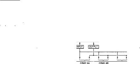
SMR I
SUPPLY
FAIL 206
ALARM
Fit,. 1.52 Loop diagram of operational interlocks for transformer or interconnector
|
|
|
SOURCE |
SOURCE 2 |
r 2
cei POS
riNN—Gma
CBI LOC
PLANT PROTECTION
TNTERLOCKS CB2
C82 POS
C62 LOC
PLANT PROTECTION
INTERLOCKS CBI
FIG. 1.53 1 out of 2 circuit-breaker operational interlock circuit diagram