

continuous actuators - 24.15
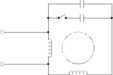
Capacitor Start and Capacitor Run Motor
Vin |
running |
|
winding |
running capacitor
starting capacitor |
squirrel cage |
rotor |
starting winding |
Figure 24.13 Single Phase Motor Configurations
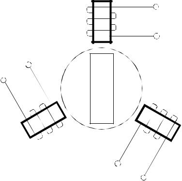
24.2.3 Brushless DC Motors
Brushless motors use a permanent magnet on the rotor, and use windings on the stator. Therefore there is no need to use brushes and a commutator to switch the polarity of the voltage on the coil. The lack of brushes means that these motors require less maintenance than the brushed DC motors.
A typical Brushless DC motor could have three poles, each corresponding to one power input, as shown in Figure 24.14. Each of coils is separately controlled. The coils are switched on to attract or repel the permanent magnet rotor.
continuous actuators - 24.16
V1
N
V2
S
V3
Figure 24.14 A Brushless DC Motor
To continuously rotate these motors the current in the stator coils must alternate continuously. If the power supplied to the coils was a 3-phase AC sinusoidal waveform, the motor will rotate continuously. The applied voltage can also be trapezoidal, which will give a similar effect. The changing waveforms are controller using position feedback from the motor to select switching times. The speed of the motor is proportional to the frequency of the signal.
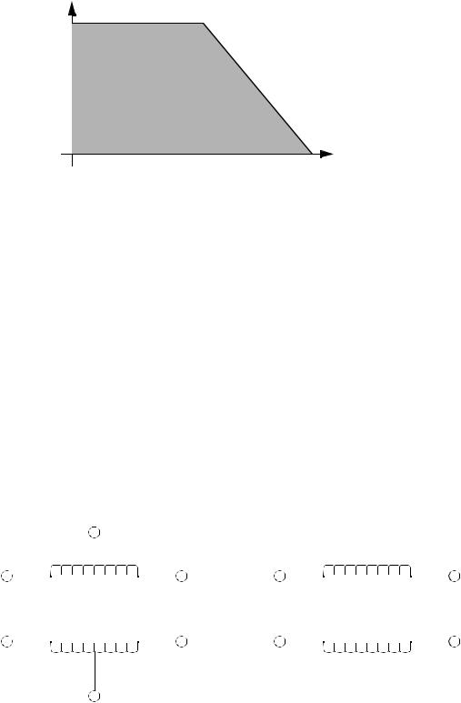
A typical torque speed curve for a brushless motor is shown in Figure 24.15.
continuous actuators - 24.17
torque |
speed |
Figure 24.15 Torque Speed Curve for a Brushless DC Motor
24.2.4 Stepper Motors
Stepper motors are designed for positioning. They move one step at a time with a typical step size of 1.8 degrees giving 200 steps per revolution. Other motors are designed for step sizes of 1.8, 2.0, 2.5, 5, 15 and 30 degrees.
There are two basic types of stepper motors, unipolar and bipolar, as shown in Figure 24.16. The unipolar uses center tapped windings and can use a single power supply. The bipolar motor is simpler but requires a positive and negative supply and more complex switching circuitry.
1
a |
|
|
|
|
b |
1a |
|
|
|
1b |
|
|
|
|
|||||||
|
|
|
|
|
|
|
|
|
|
|
a |
|
|
|
b |
2a |
|
|
|
2b |
|
|
|
|
|
|
|
|
|
|
2
unipolar |
bipolar |
continuous actuators - 24.18
Figure 24.16 Unipolar and Bipolar Stepper Motor Windings
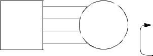
The motors are turned by applying different voltages at the motor terminals. The voltage change patterns for a unipolar motor are shown in Figure 24.17. For example, when the motor is turned on we might apply the voltages as shown in line 1. To rotate the motor we would then output the voltages on line 2, then 3, then 4, then 1, etc. Reversing the sequence causes the motor to turn in the opposite direction. The dynamics of the motor and load limit the maximum speed of switching, this is normally a few thousand steps per second. When not turning the output voltages are held to keep the motor in position.
1a |
|
|
2a |
stepper |
|
controller |
||
motor |
||
1b |
||
2b |
|
Step |
1a |
2a |
1b |
2b |
|
|
|
|
|
1 |
1 |
0 |
1 |
0 |
2 |
0 |
1 |
1 |
0 |
3 |
0 |
1 |
0 |
1 |
4 |
1 |
0 |
0 |
1 |
To turn the motor the phases are stepped through 1, 2, 3, 4, and then back to 1. To reverse the direction of the motor the sequence of steps can be reversed, eg. 4, 3, 2, 1, 4, ..... If a set of outputs is kept on constantly the motor will be held in position.
Figure 24.17 Stepper Motor Control Sequence for a Unipolar Motor
Stepper motors do not require feedback except when used in high reliability applications and when the dynamic conditions could lead to slip. A stepper motor slips when the holding torque is overcome, or it is accelerated too fast. When the motor slips it will move a number of degrees from the current position. The slip cannot be detected without position feedback.
Stepper motors are relatively weak compared to other motor types. The torque speed curve for the motors is shown in Figure 24.18. In addition they have different static and dynamic holding torques. These motors are also prone to resonant conditions because of the stepped motion control.