

- •Table of Contents
- •About the Author
- •About the Technical Reviewer
- •Acknowledgments
- •Software Entropy
- •Clean Code
- •C++11: The Beginning of a New Era
- •Who This Book Is For
- •Conventions Used in This Book
- •Sidebars
- •Notes, Tips, and Warnings
- •Code Samples
- •Coding Style
- •C++ Core Guidelines
- •Companion Website and Source Code Repository
- •UML Diagrams
- •The Need for Testing
- •Unit Tests
- •What About QA?
- •Rules for Good Unit Tests
- •Test Code Quality
- •Unit Test Naming
- •Unit Test Independence
- •One Assertion per Test
- •Independent Initialization of Unit Test Environments
- •Exclude Getters and Setters
- •Exclude Third-Party Code
- •Exclude External Systems
- •What Do We Do with the Database?
- •Don’t Mix Test Code with Production Code
- •Tests Must Run Fast
- •How Do You Find a Test’s Input Data?
- •Equivalence Partitioning
- •Boundary Value Analysis
- •Test Doubles (Fake Objects)
- •What Is a Principle?
- •KISS
- •YAGNI
- •It’s About Knowledge!
- •Building Abstractions Is Sometimes Hard
- •Information Hiding
- •Strong Cohesion
- •Loose Coupling
- •Be Careful with Optimizations
- •Principle of Least Astonishment (PLA)
- •The Boy Scout Rule
- •Collective Code Ownership
- •Good Names
- •Names Should Be Self-Explanatory
- •Use Names from the Domain
- •Choose Names at an Appropriate Level of Abstraction
- •Avoid Redundancy When Choosing a Name
- •Avoid Cryptic Abbreviations
- •Avoid Hungarian Notation and Prefixes
- •Avoid Using the Same Name for Different Purposes
- •Comments
- •Let the Code Tell the Story
- •Do Not Comment Obvious Things
- •Don’t Disable Code with Comments
- •Don’t Write Block Comments
- •Don’t Use Comments to Substitute Version Control
- •The Rare Cases Where Comments Are Useful
- •Documentation Generation from Source Code
- •Functions
- •One Thing, No More!
- •Let Them Be Small
- •“But the Call Time Overhead!”
- •Function Naming
- •Use Intention-Revealing Names
- •Parameters and Return Values
- •Avoid Flag Parameters
- •Avoid Output Parameters
- •Don’t Pass or Return 0 (NULL, nullptr)
- •Strategies for Avoiding Regular Pointers
- •Choose simple object construction on the stack instead of on the heap
- •In a function’s argument list, use (const) references instead of pointers
- •If it is inevitable to deal with a pointer to a resource, use a smart one
- •If an API returns a raw pointer...
- •The Power of const Correctness
- •About Old C-Style in C++ Projects
- •Choose C++ Strings and Streams over Old C-Style char*
- •Use C++ Casts Instead of Old C-Style Casts
- •Avoid Macros
- •Managing Resources
- •Resource Acquisition Is Initialization (RAII)
- •Smart Pointers
- •Unique Ownership with std::unique_ptr<T>
- •Shared Ownership with std::shared_ptr<T>
- •No Ownership, but Secure Access with std::weak_ptr<T>
- •Atomic Smart Pointers
- •Avoid Explicit New and Delete
- •Managing Proprietary Resources
- •We Like to Move It
- •What Are Move Semantics?
- •The Matter with Those lvalues and rvalues
- •rvalue References
- •Don’t Enforce Move Everywhere
- •The Rule of Zero
- •The Compiler Is Your Colleague
- •Automatic Type Deduction
- •Computations During Compile Time
- •Variable Templates
- •Don’t Allow Undefined Behavior
- •Type-Rich Programming
- •Know Your Libraries
- •Take Advantage of <algorithm>
- •Easier Parallelization of Algorithms Since C++17
- •Sorting and Output of a Container
- •More Convenience with Ranges
- •Non-Owning Ranges with Views
- •Comparing Two Sequences
- •Take Advantage of Boost
- •More Libraries That You Should Know About
- •Proper Exception and Error Handling
- •Prevention Is Better Than Aftercare
- •No Exception Safety
- •Basic Exception Safety
- •Strong Exception Safety
- •The No-Throw Guarantee
- •An Exception Is an Exception, Literally!
- •If You Can’t Recover, Get Out Quickly
- •Define User-Specific Exception Types
- •Throw by Value, Catch by const Reference
- •Pay Attention to the Correct Order of Catch Clauses
- •Interface Design
- •Attributes
- •noreturn (since C++11)
- •deprecated (since C++14)
- •nodiscard (since C++17)
- •maybe_unused (since C++17)
- •Concepts: Requirements for Template Arguments
- •The Basics of Modularization
- •Criteria for Finding Modules
- •Focus on the Domain of Your Software
- •Abstraction
- •Choose a Hierarchical Decomposition
- •Single Responsibility Principle (SRP)
- •Single Level of Abstraction (SLA)
- •The Whole Enchilada
- •Object-Orientation
- •Object-Oriented Thinking
- •Principles for Good Class Design
- •Keep Classes Small
- •Open-Closed Principle (OCP)
- •A Short Comparison of Type Erasure Techniques
- •Liskov Substitution Principle (LSP)
- •The Square-Rectangle Dilemma
- •Favor Composition over Inheritance
- •Interface Segregation Principle (ISP)
- •Acyclic Dependency Principle
- •Dependency Inversion Principle (DIP)
- •Don’t Talk to Strangers (The Law of Demeter)
- •Avoid Anemic Classes
- •Tell, Don’t Ask!
- •Avoid Static Class Members
- •Modules
- •The Drawbacks of #include
- •Three Options for Using Modules
- •Include Translation
- •Header Importation
- •Module Importation
- •Separating Interface and Implementation
- •The Impact of Modules
- •What Is Functional Programming?
- •What Is a Function?
- •Pure vs Impure Functions
- •Functional Programming in Modern C++
- •Functional Programming with C++ Templates
- •Function-Like Objects (Functors)
- •Generator
- •Unary Function
- •Predicate
- •Binary Functors
- •Binders and Function Wrappers
- •Lambda Expressions
- •Generic Lambda Expressions (C++14)
- •Lambda Templates (C++20)
- •Higher-Order Functions
- •Map, Filter, and Reduce
- •Filter
- •Reduce (Fold)
- •Fold Expressions in C++17
- •Pipelining with Range Adaptors (C++20)
- •Clean Code in Functional Programming
- •The Drawbacks of Plain Old Unit Testing (POUT)
- •Test-Driven Development as a Game Changer
- •The Workflow of TDD
- •TDD by Example: The Roman Numerals Code Kata
- •Preparations
- •The First Test
- •The Second Test
- •The Third Test and the Tidying Afterward
- •More Sophisticated Tests with a Custom Assertion
- •It’s Time to Clean Up Again
- •Approaching the Finish Line
- •Done!
- •The Advantages of TDD
- •When We Should Not Use TDD
- •TDD Is Not a Replacement for Code Reviews
- •Design Principles vs Design Patterns
- •Some Patterns and When to Use Them
- •Dependency Injection (DI)
- •The Singleton Anti-Pattern
- •Dependency Injection to the Rescue
- •Adapter
- •Strategy
- •Command
- •Command Processor
- •Composite
- •Observer
- •Factories
- •Simple Factory
- •Facade
- •The Money Class
- •Special Case Object (Null Object)
- •What Is an Idiom?
- •Some Useful C++ Idioms
- •The Power of Immutability
- •Substitution Failure Is Not an Error (SFINAE)
- •The Copy-and-Swap Idiom
- •Pointer to Implementation (PIMPL)
- •Structural Modeling
- •Component
- •Interface
- •Association
- •Generalization
- •Dependency
- •Template and Template Binding
- •Behavioral Modeling
- •Activity Diagram
- •Action
- •Control Flow Edge
- •Other Activity Nodes
- •Sequence Diagram
- •Lifeline
- •Message
- •State Diagram
- •State
- •Transitions
- •External Transitions
- •Internal Transitions
- •Trigger
- •Stereotypes
- •Bibliography
- •Index
Appendix A Small UML Guide
Interface
An interface defines a kind of a contract. A component or class that realizes the interface must fulfill that contract. Another component or class that uses the interface expects that it is supplied with an element that fulfills the contract.
INTERFACE
An interface is a declaration of a set of coherent public obligations.
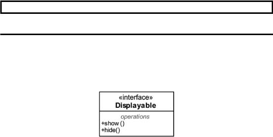
Interfaces are always abstract, that is, they cannot be instantiated by default. The UML symbol for an interface is very similar to a class, with the keyword «interface» above its name, as depicted in Figure A-6.
Figure A-6. The Displayable interface with two declared operations
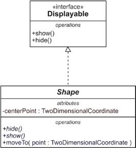
To express, for example, that a class realizes (synonym: implements) an interface, a special relationship exists in UML. The realization relationship is a dashed arrow with a closed but not filled arrowhead. This relationship points, as depicted in Figure A-7, from the class (the realizing element) to the interface (the specification).
457
Appendix A Small UML Guide
Figure A-7. The Shape class realizes the Displayable interface
It is, of course, allowed that a class implements multiple interfaces.
Unlike some other object-oriented languages, such as Java and C#, there is no interface keyword in C++. Interfaces are therefore usually emulated with the help of abstract classes that solely consist of pure virtual member functions, as shown in Listing A-2.
Listing A-2. The Displayable Interface in C++
class Displayable { public:
virtual ~Displayable() = default; virtual void show() = 0;
virtual void hide() = 0;
};
To show that a class or component provides or requires interfaces, you can use the so-called ball-and-socket notation. A provided interface is depicted using a ball (a “lollipop”), whereas a required interface is depicted with a socket (a symbol that looks like a claw). Strictly speaking, this is an alternative notation, as Figure A-8 clarifies. (The association relationship that appears in this figure between Account and Owner is explained in detail in the following section.)
458

Appendix A Small UML Guide
Figure A-8. The so-called “ball-and-socket-notation” for provided (AccountService) and required (Owner) interfaces
Association
Classes usually have static relationships to other classes. The UML association specifies such a relationship.
ASSOCIATION
An association relationship allows one instance of a classifier (e.g., a class or a component) to access another.
In its simplest form, the UML syntax for an association is a solid line between two classes, as depicted in Figure A-9.
459
Appendix A Small UML Guide
Figure A-9. A simple association relationship between two classes
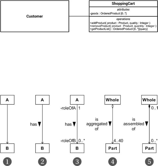
This simple association is often not sufficient to properly specify the relationship between both classes. For instance, the navigation direction across such a simple association, that is, who is able to access whom, is undefined by default. However, navigability in this case is often interpreted as bidirectional by convention, that is, Customer (whose internals have been completely hidden here) has an attribute to access ShoppingCart and vice versa. Therefore, more information can be provided to an association. Figure A-10 illustrates a few of the possibilities.
Figure A-10. Some examples of associations between classes
\ 1.\ This example shows an association with one end navigable (depicted by an arrowhead) and the other having unspecified navigability. The semantic is: class A is able to navigate to class B. In the other direction it is unspecified, that is, class B might be able to navigate to class A.
460

Appendix A Small UML Guide
Note It is strongly recommended to define the interpretation of the navigability of such an unspecified association end in your project. My recommendation is to consider them as non-navigable. This interpretation is also used in this book.
\2.\ This navigable association has a name (“has”). The solid triangle indicates the direction of reading. Apart from that, the semantics of this association is fully identical to Example 1.
\3.\ In this example, both association ends have labels (names) and multiplicities. The labels are typically used to specify the roles of the classes in an association.
A multiplicity specifies the allowed quantity of instances of the classes that are involved in an association. It is an inclusive interval of non-negative integers beginning with a lower bound and ending with an (possibly infinite) upper bound. In this case, any A has zero to any number of Bs, whereas any B has exactly one A. Table A-2 shows some examples of valid multiplicities.
\4.\ This is a special association called aggregation. It represents a whole-part-relationship; that is, the one class (the part) is hierarchically subordinated to the other class (the whole). The hollow diamond is just a marker in this kind of association and identifies the whole. Otherwise, everything that applies to associations applies to an aggregation.
\5.\ This is a composite aggregation, which is a strong form of aggregation. It expresses that the whole is the owner of the parts, and thus also responsible for the parts. If an instance of the whole is deleted, all of its part instances are normally deleted with it.
Note Note that a part can (where allowed) be removed from a composite before the whole is deleted, and thus not be deleted as part of the whole. This can be made possible by a multiplicity of 0..1 at the association end that is connected to the whole, that is, the end with the filled diamond. The only allowed multiplicities at this end are 1 or 0..1; all other multiplicities are prohibited.
461