

Экзамен зачет учебный год 2023 / Stoter, 3D Cadastre
.pdf12.1. Prototypes of the hybrid cadastre
(a) All the parcels are encumbered by right of superficies, new parcels are created for all intersecting parcels
(b) As figure (a), but now three newly created parcels are in full ownership
(c) Three newly created parcels are in full ownership, two parcels that are not subdivided are in full ownership. All the other (new) parcels are encumbered by a right of superficies
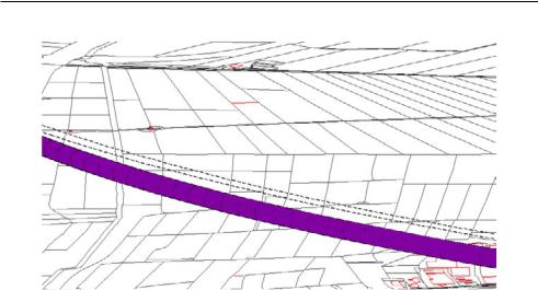
Figure 12.7: Three possible recordings of 3D right-volumes in the case of a railway tunnel.
the 3D representation relates to the actual construction. The location of the tunnel helps to better understand the real situation.
265
Chapter 12. Prototypes applied to case studies
Figure 12.8: Registration of the 3D physical object in the case of the HSL tunnel. The dashed line is the projection of the tunnel on the surface. Note that the parcels are not divided into smaller parcels.
12.1.6Evaluation of hybrid cadastre
When a juridical framework cannot entitle persons to volumes independent from the surface, the 3D cadastre can be implemented within a hybrid environment introducing either 3D right-volumes or a physical object registration.
3D right-volumes
From the prototype implementations it can be concluded that the introduction of 3D right-volumes means a significant improvement of current cadastral registration in 3D situations. The inclusion of 3D right-volumes in the cadastral geographical data set provides an overview of the distribution of 3D property units. The registration warns the user of the cadastral registration that something is located under or above the surface. It also gives information on what is located under or above the surface (relationship with whole real estate object is maintained). For precise information the deed in the land registration can be consulted. A 3D survey of the situation can be made and used to describe the situation in the deeds and to determine the upper and lower limits of 3D right-volumes. From a technical point of view, the geometry of 3D right-volumes is simple and can therefore be maintained in the DBMS within current techniques.
Basic disadvantages of 3D right-volumes are:
•Since parcels are still the basis for registration, gaps can occur when no rights have been established that require a cadastral recording, e.g. when the holder of the construction is the same as the owner of the intersecting parcel. In these cases the location of the construction is still not known in the cadastral registration.
•If rights are established on just a part of a parcel, new parcel boundaries need to be created. This leads to fragmentation of both parcels and 3D right-volumes.
266

12.1. Prototypes of the hybrid cadastre
•When space where the right applies to is not precisely restricted in height or depth, registration of 3D right-volumes does not give satisfying insight, as was seen in the Rijswijk case. This could be solved by a rule applying to 3D surveys that will allow open polyhedrons (either not defined in height or in depth).
•Horizontal boundaries restrict the spatial description of 3D right-volumes. The concept of a 3D right-volume could be improved when other than just horizontal boundaries could be defined.
Registration of 3D physical objects
From the experiments with the case studies it can be concluded that a registration of physical objects o ers several improvements. The 3D description of the physical objects (extent of the object) can be used for reference purposes (to improve the reflection of the real situation) and to support cadastral tasks. When a 3D physical object is registered parcels do not need to be divided into parcels matching with the 2D projection of the physical object since the exact location of the physical object is known in the cadastral database. Only one object needs to be registered by which the registration for all intersecting parcels can be guaranteed. All parcels intersecting with the physical object can be found by a spatial query (by an overlay with the projection of the 3D object).
From a technical point of view the geometry that has to be maintained for physical objects can become complex. It is therefore not easy and straightforward to insert and maintain the spatial information on 3D physical objects within current techniques.
Conclusion on hybrid cadastre
In both alternatives, rights to hold 3D property units are still registered on the intersecting parcels. Querying the legal status of 3D property units still needs to be done by querying the legal status of the intersecting parcels. However the maintenance of the 3D situation can assist considerably in understanding the real situation. Cadastral registrations that are not yet ready for a full 3D cadastre, will benefit for a number of reasons from a hybrid registration:
•The solutions give visual insight into 3D into the real situation. It is now clear from the cadastral registration that persons are entitled to space above or under the surface.
•Both solutions are implemented within the cadastral registration as part of the cadastral geographical data set and can therefore be queried with parcel surfaces in one integrated view.
•The proposed solutions show notaries how the inclusion of spatial information in deeds can be used to visualise the 3D component of rights in the cadastral registration. The solution can make notaries aware of the improvements of 3D registration and may motivate them to include well-defined 3D information in the deeds or to require a 3D survey plan.
•Registrations and databases outside the cadastral domain can benefit from the information on 3D situations that is available in the cadastral registration and vice versa via the Geo-Information Infrastructure (monument registration, building registration, taxes for immovable goods, management of soil pollution areas, management of cables and pipes, management of the subsurface).
267

Chapter 12. Prototypes applied to case studies
The case studies were divided into building complexes and infrastructure objects. A physical object relating to a property unit within a building complex coincides with the legal space of a property unit. The main objective of cadastral registration in the case of building complexes is to give insight in property boundaries in all dimensions rather than to reflect the built constructions in the cadastral registration for reference purposes. On the other hand, the main objectives of a registration of 3D physical objects are firstly to be able to locate infrastructure objects to support cadastral tasks and secondly to register the person who holds an infrastructure object. Therefore the registration of 3D physical objects will specifically be suitable for infrastructure objects. For registering property units in building complexes, 3D right-volumes are more appropriate, because the spatial extent of properly units can be easily and clearly defined with 3D right-volumes which refer to the legal space to which a person is entitled.
The two concepts of the hybrid cadastre (3D right-volumes and 3D physical object registration) have a di erent line of approach and therefore meet other needs of 3D cadastral registration. The 3D right-volume is a considerable improvement of insight into 3D property units as part of the cadastral geographical data set, while the 3D physical object registration provides information on constructions which is available in the cadastral geographical data set to improve the reflection of the real situation. The concepts could be combined to take advantage of both solutions.
The main limitation of both hybrid solutions is that the property rights are still related to surface parcels.
12.2Prototype of the full 3D cadastre
In the full 3D cadastre it is possible to entitle a person to a volume parcel that is no longer related to the surface parcel (only in the case when it is subdivided from the infinite parcel column defined by the surface parcel). Section 12.2.1 will describe the results of the prototype applied to the case study in Queensland, while section 12.2.2 will evaluate the prototype of the full 3D cadastre.
12.2.1The Gabba Stadium in Queensland
As was seen in section 4.6, the juridical framework in Queensland, as in some other countries and states, provides a good basis for a full 3D cadastre. Within this framework it is possible to establish property rights to 1) standard, infinite parcels, 2) volumetric parcels (no longer related to the surface) and 3) remainder parcels that are left after a volumetric parcel has been subtracted from a standard parcel. In our model volumetric parcels are referred to as ‘volume parcels’.
The cadastral framework in Queensland does not yet provide the possibility to maintain the 3D geometry of the volumetric parcels in the cadastral registration. In section 4.6 it was concluded that the current cadastral registration of volumetric properties, in which only the 2D geometry is registered, meets the following limitations:
268

12.2. Prototype of the full 3D cadastre
•Since the 3D information is laid down on paper (or scanned) drawings (which is a 2D visualisation of 3D information), the 3D information cannot be interactively viewed.
•The 3D properties are only described by coordinates and faces on drawings, i.e. no 3D primitive is used. Therefore it is not possible to check if a valid 3D property has been established. Is the 3D property closed? Are the faces planar?
•The 3D information is not integrated with the cadastral map or with other 3D information, e.g. two or more neighbouring parcels cannot be visualised in one view in 3D and it is also not possible to check how volumetric parcels spatially interact in 3D (overlap, touch, etc.).
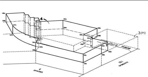
To improve cadastral registration we applied the feasible concept of the full 3D cadastre (combination of volume parcels and infinite parcel columns) to the described case study in Queensland; the Gabba Stadium in Brisbane at the location of Vulture Street (in the north), i.e. parcel 100 (stratum parcel) and parcel 101 (volumetric parcel), see figure 4.3 and 12.9.
Figure 12.9: Volumetric parcel (101) and stratum parcel (100) used in the case study.
269

Chapter 12. Prototypes applied to case studies
The required survey plans for the volumetric parcel and the stratum parcel contain 3D information that can be used to describe the 3D geometry and the 3D topological structure of these objects in the cadastral database. The following steps were followed to convert the spatial information on the (scanned) 3D survey plans into a 3D geometrical primitive in the DBMS:
•The field measurements, as indicated on the survey plan by distances and bearings between the successive points, were adjusted by traverse adjustment for each parcel in a local coordinate system [209].
•The local rectangular coordinates are fitted to the (global) map coordinates by an over determined conformal (Helmert) transformation using three connections points in both coordinate systems [209].
•The faces were constructed with references to nodes.
•This information was inserted in a 3D topological structure (SSM) in the DBMS.
•From the topological structure the geometry (as polyhedron primitive) can be realised, validated and (spatially) queried using the self-implemented 3D primitive and 3D functions.
After these steps the 3D geometries could be visualised and queried in one integrated view (see figure 12.10), which o ers major improvements. It is now possible to see if and how the volumetric parcels interact and to view the 3D situation interactively.
The neighbouring polygons as defined do not match face to face; comparing the common boundary between parcel 100 and 101 shows a di erence of about 30 centimetres (see figure 12.10 (b)).
(a) |
(b) |
Figure 12.10: Visualisation of 3D geometries of volumetric parcels, stored in DBMS. Zoom-in on shared faces (b) shows that the shared faces do not coincide.
This may indicate an error but in this case it is correct. The two parts were determined at di erent times, and parcel 101 allows more space around the structure. The measurements define the space while there is no real object to mark the limits of the parcels. Therefore the geometry of the volume parcels must by definition be correct.
270

12.2. Prototype of the full 3D cadastre
In order to validate the volumetric parcels and to perform 3D spatial functions on the volumetric parcels, the geometry of the volumetric parcels was represented using the self-implemented 3D geometrical primitive (section 7.4).
Therefore we were able to query the 3D objects in an integrated DBMS environment:
/* validate of 3D geometries */
SELECT bid, validate_polyhedron(return_polyhedron(shape), 0.5) validate FROM qld_3Dgeom;
BID VALIDATE
---- ----------
100True
101True
/* calculate volumes of 3D geometries
SELECT bid, volume(return_polyhedron(shape)) volume FROM qld_3Dgeom;
BID VOLUME
---- ----------
10012725.1989
1015329.18583
/* check if two geometries intersect (1=TRUE and 0=FALSE) */ SELECT d1.bid, d2.bid FROM robject3dql d1, robject3dql d2
WHERE intersection(return_polyhedron(d1.shape), return_polyhedron(d2.shape),0.01) = 1 AND d1.bid < d2.bid;
BID |
BID |
------ |
------ |
100 |
101 |
The 3D geometries can be incorporated in a cadastral geographical data set that contains surface parcels represented in 2.5D in order to get a 3D overview of the complete situation. For this purpose a conforming TIN was generated using ESRI software that incorporated the planar partition of the cadastral base map (see chapter 9). The result is shown in figure 12.11.
12.2.2Evaluation of full 3D cadastre
As can be concluded from this case study, the full 3D cadastre o ers many improvements compared to traditional cadastral registrations:
•The real situation is no longer projected on the surface, i.e. volumetric parcels are not dominated by the parcel pattern on the surface.
•Persons can be entitled to space in a transparent way instead of establishing property rights on intersecting parcels to establish the legal status above and below the surface.
•The space is precisely described in a 3D survey document, which o ers a uniform way of defining 3D property units.
271

Chapter 12. Prototypes applied to case studies
(a) |
(b) |
(c)
Figure 12.11: Visualisation of 3D geometries of volumetric parcels together with the 2.5D cadastral base map, seen from di erent view points.
The full 3D cadastre also o ers improvements in countries and states that already establish 3D property units unrelated to the surface:
•The information from the 3D survey document can be used to insert the volume parcels in a topological structure and in geometrical primitives in the DBMS.
•The volume parcels can be viewed interactively.
•The geometry of volume parcels can be checked, e.g. are the faces planar, is the volume closed, are there no self-intersections?
•The 3D situation can be (spatially) queried in the DBMS (e.g. do volume parcels intersect?).
•The volume parcels can be visualised in an integrated view with a 2.5D representation of the parcels that are defined by parcel boundaries on the surface.
•The volume parcels and the 2.5D surface parcels can be queried in the DBMS, e.g. is the volume parcel located above or below the surface, or does it intersect the surface?
272

12.2. Prototype of the full 3D cadastre
The advantage of having the 3D property unit in the same environment as the 2D parcels clearly o ers great potentials. However, even starting from one of the more advanced environments (Queensland, where both the legal aspects and the 3D survey documents are satisfactory dealt with) quite a number of non-trivial issues still need to be addressed:
•In the survey plans both the 3D points and edges are specified (as required), however there is no explicit listing of faces and the polyhedron itself. It is not trivial to reconstruct the faces and it is possibly ambiguous, especially in more complex cases (such as parcel 103 in figure 4.3).
•The validation of the polyhedron is non-trivial (especially if it consists of other faces than horizontal, vertical or triangular faces). Is the volume completely closed? Are all the faces planar (enough)? Is the orientation correct? Are holes or cavities modelled correctly? etc.
•The (footprints of the) 3D objects do not fit perfectly in the cadastral map: a straightforward conversion from the local coordinates to global coordinates (rotate, translate) resulted in a mismatch of about 60 cm: additional field measurements are required to solve these di erences.
•The Queensland regulations also allow non-polyhedral 3D objects, such as (rotated) ellipsoids or cylindrical patches (see figure 12.12). Should these be converted to polyhedrons (approximation within given tolerance) to be modelled in the DBMS or should the DBMS be extended with complex 3D data types?
•Attention should be paid on how to make sure that two polyhedra do not overlap in 3D space (but at most touch in a common node, edge or face) and on how to make sure that there is no 3D sliver between two polyhedra that are supposed to be touching neighbours.
•The cadastral registration should be organised in a uniform manner. In the case study (with only three 3D objects all related to the same construction) some di erences are noticeable:
–Neighbour parcels 100 and 101 are both on the same side of the stadium, but parcel 100 is related to a stratum parcel, since it was established before 1997, and parcel 101 is related to a 3D volumetric parcel, which is only possible after 1997. Therefore the available information for the parcels di ers.
–Parcels 101 and 103 are both volumetric parcels, while parcel 101 is relatively rough, it seems that parcel 103 is defined quite tightly around the construction (making this object quite complex).
•Trivial registration errors should be avoided, such as the recording of the volume. It turned out that the recorded volume of parcel 101 in the cadastral registration was not correct (10,000 times too large), probably due to some typing error (because the survey plan was correct).
In addition to this, it is also a challenging task to integrate a terrain elevation model with the 2D surface parcels in order to obtain 2.5D surface parcels which can be combined with the 3D objects. This should preferably be implemented as an integrated view (in the DBMS sense) on the two data sets from the independent, distributed sources and not as a physical (permanent) integration with copies of the data sets (see chapter 9).
273
Chapter 12. Prototypes applied to case studies
Figure 12.12: Volumetric parcel defined with more complex geometry than polyhedron.
In areas with high density of 3D volume parcels a true space partitioning might be needed (defined in a full topological model).
12.3Conclusions
In this chapter the concepts of the hybrid cadastre and the full 3D cadastre were applied to case studies in order to evaluate the concepts.
Hybrid cadastre
3D right-volumes
The experiments with the case studies showed that 3D right-volumes considerably improve insight into the property situation in 3D property situations. It is now clear how property units are distributed in 3D. Generating and maintaining spatial data is easy when registering 3D right-volumes: the parcel boundaries that are already registered form the basis for the 3D representations while the geometry of 3D rightvolumes is simple. A disadvantage of 3D right-volumes is when no limited rights have been established on a parcel in a 3D situation. These cases are not registered in the cadastral registration and therefore they lead to gaps in the 3D registration. Another disadvantage is when rights are not clearly restricted in the vertical dimension in the deed. In the first case, gaps occur in the registration and in the second case the 3D right-volume does not necessarily yield more insight than in current cadastral registration as was seen in the Rijswijk case. In the case of apartment units, the 2D boundary of 3D right-volumes did not coincide with the parcel boundary. However if drawings added to deeds of divisions would be available in vector format and in worldcoordinates the spatial information from the drawings can be used to automatically produce the 2D description of 3D right-volumes for every floor. These polygons can then be used to generate the 3D right-volumes. The 3D right-volume concept could be improved if the boundaries between two 3D right-volumes on top of each other were not restricted to horizontal boundaries. Non-horizontal boundary can reflect
274