

Экзамен зачет учебный год 2023 / Stoter, 3D Cadastre
.pdf11.4. Maintaining history in the 3D cadastre
construction and also when the geometry of a volume parcel is complex. The 3D survey plan should define how the volume parcel is bounded by defining all the corner coordinates with x, y, and z-coordinates in the National Height Datum. The insertion of volume properties in the cadastral database makes it possible to check the volume property (is the property closed, are all faces planar) and to check the constraints to assure the topological partition of space (the volume property should not intersect another volume property; the volume property should not intersect a parcel on which no volume properties have been established). After these checks the geometry of the volume property can be inserted into the cadastral geographical data set.
A procedure should be developed and defined to convert the 3D survey into an internal topological structure and into geometrical primitives in the database. If this procedure is clear, the process from surveying to insertion in the cadastral database can be streamlined. In the prototype the whole process from 3D survey plan to geometrical and topological representations in the cadastral database has been implemented.
11.3.4Querying
The queries that are supported by the full 3D cadastre are:
•Is this volume parcel valid (closed, planar faces)?
•Are these volume parcels overlapping? (This query can be used in constraints.)
•Is this volume parcel intersecting a parcel that is defined by an infinite parcel column (can be used in constraints)?
•To what space is this person entitled?
•Does this parcel refer to an infinite or a remainder parcel?
•What are the 3D neighbours of this parcel or volume parcel?
•Show the cadastral map in 3D.
11.4Maintaining history in the 3D cadastre
When the registration of 3D physical objects, 3D right-volumes or 3D volume parcel becomes practise, updates will occur by which version managing is necessary, which is the 4D aspect of data modelling. The current cadastral DBMS maintains history as described in [136] in a self-implemented extension since history is not supported by mainstream DBMSs. History is currently maintained at record level (only for the spatial part of the cadastral database). For every object (parcel and boundary) a start-time and an end-time are stored. When an object is created the current time is set as start-time in the new record and a time in the faraway future is set as end-time. This is necessary to be able to reconstruct the correct situation at any given point in history, e.g. give me the cadastral map of October 10th, 1988. The unique identifier for objects (key) is the pair (object-id, start-time). Only when a new object is created or an old-object is drastically changed (e.g. subdivided) a new object-id will be used. For simple updates a creation of a new object version (with same object-id) is the way to capture full history.
245

Chapter 11. Logical model for a 3D cadastre
This structure assures topologically consistent data. For topological references, only the object-id is used to refer to another object. In the situation that a referred object is updated and keeps its object-id, the reference does not change. This avoids in a topologically structured data set, the propagation of changes for many objects when only one object is changed as all objects are somehow connected to each other. In case the object-id of a referred object is changed (becomes a di erent object), the referring object has also to be updated.
11.4.1History for 3D right-volumes
History for 3D right-volumes can be maintained in a similar way if we assume that the 3D internal topological structure is the basic structure that is maintained. When the face is the lowest dimensional topological object, history can be maintained on faces similar to parcel boundaries. When a face is moved, the face is updated. If this is not seen as a major adjustment, no new object-id will be created for the face. The 3D geometrical description of 3D right-volumes will change because the object consists of references to the faces which are updated. When nodes are the lowest dimensional objects, the same apply for nodes (nodes are updated and the geometrical description of faces and 3D right-volumes change through their references). When a new object-id is created for lower-dimensional objects, the change of such an object will propagate changes in the higher-dimensional objects that refer to these objects. Topological consistency of di erent time stamps should therefore always be checked while updating.
11.4.2History for 3D physical objects
History on the geometry of 3D physical objects can be maintained on the whole object. A start-time and an end-time are maintained as attributes for 3D physical objects. Updates work in the same way as updates of parcel boundaries. A new object version will be created and the old one will be ended when an update occurs. Since no topology is maintained between 3D physical objects, updates of 3D physical objects do not a ect other 3D physical objects. However, consistency checks should assure that 3D physical objects, also in the new situation, do not overlap. In addition, changes will a ect other objects that contain references to the physical objects (e.g. where the holder of a physical object refers explicitly to the physical object or where the relationship between parcels and physical objects is maintained explicitly).
11.4.3History in a full 3D cadastre
In case of a full 3D cadastre, the history can be maintained in the same way as in current registration if we assume that both the 2.5D topological structure is maintained (for infinite and remainder parcels) as well as the internal 3D topological structure and a full partition of space in densely built-up areas. If the lower dimensional objects are updated and no new object-ids are created, the geometrical description of the higher dimensional objects will change through the defined references. However,
246

11.5. Conclusions
in the new situation consistency checks should assure that 3D right-volumes do not overlap in 3D. Updates of an object (surface parcel or volume parcel) should result in a new object-id if the updates are major changes (e.g. in case of a subdivision) to avoid losing some of the history. In this process topological consistency of di erent time stamps needs special attention.
11.5Conclusions
This chapter described the issues that need to be considered when translating the conceptual models of 3D right-volumes, 3D physical objects and the full 3D cadastre into logical models for the selected object relational database structure.
Concerning spatial models, current techniques are appropriate for modelling (the simple) geometry of 3D right-volumes and for modelling simple volume parcels, although the 3D topology structure needs more research (e.g. implementing consistency checks as part of the DBMS).
Geometry of both 3D physical objects and complex volume parcels is harder to model within current techniques. In order to precisely define the geometry of 3D physical objects and complex volume parcels in the DBMS, research is needed on storing complex 3D geometries (more complex than a polyhedron) in a DBMS. Topology between objects in the proposed solutions for a 3D cadastre (3D right-volumes, 3D physical objects and volume parcels) is not needed, only in the case of volume parcels in densely built-up areas. Spatial relationships between two 3D geo-objects can be obtained by spatial functions. Topology forms therefore no bottleneck for implementing the logical models of these objects, except in the case a full 3D partition is needed.
Populating the spatial data models with data was another issue that was considered in this chapter. The data collection in case of 3D right-volumes and volume parcels requires 3D surveys instead of 2D surveys. Procedures should be set up that regulates the content of 3D survey plans (what data should be incorporated and how?). In case of 3D physical objects one could think of using the CAD designs of the physical objects. However, as was described in this chapter, it is not straightforward to convert a CAD design to a GIS model (i.e. a collection of objects geometrically defined in realworld coordinates, with both spatial and non-spatial attributes).
Apart from spatial and administrative modelling, 4D requirements for the logical models were also considered in this chapter: how to maintain history. History is not supported in current DBMSs. However history in the three logical models for the 3D cadastre could basically follow the same approach as history is currently implemented in the cadastral DBMS, where spatial objects have two additional attributes (tmin and tmax) to implement history.
Based on the considerations for the logical models as described in this chapter, the prototypes were implemented. The prototypes contain the basic aspects of the three selected alternatives. In chapter 12 the prototypes will be evaluated as well as the conceptual and logical models of the di erent alternatives, by applying the prototypes to the case studies introduced earlier in this research.
247
Part IV
Realisation of a 3D cadastre
249
Chapter 12
Prototypes applied to case studies
Three conceptual models of a 3D cadastre (the registration of 3D right-volumes, 3D physical objects and the registration of volume parcels) were completed in chapter 10. The considerations for translating these conceptual models into logical models for an object relational database structure were described in chapter 11. To evaluate the conceptual models, the two logical models of the hybrid cadastre (the registration of 3D right-volumes and the registration of 3D physical objects) were populated with data concerning the Dutch 3D property situations introduced in chapter 3. The logical model for the combined 2D/3D alternative of the full 3D cadastre (volume parcels and infinite parcel columns) was populated with data concerning the case study from Queensland, Australia introduced in chapter 4. The reason for this was that the juridical doctrine in Queensland provides already the possibility of establishing multilevel ownership, while in the Netherlands the property to real estate is still land (surface) oriented (as in the hybrid case). The prototype implementations applied to the case studies resulted in an evaluation of possibilities and constraints of the proposed conceptual models.
Section 12.1 describes the prototypes of the hybrid cadastre applied to the Dutch 3D property situations. Section 12.2 describes the full 3D cadastre prototype applied to the case study in Queensland, Australia.
The chapter ends with conclusions.
For the prototype implementations the technical framework that was explored in part II of this thesis was used. The 3D data are maintained in Oracle Spatial 9i. The data are accessed with both MicroStation GeoGraphics and Web based techniques (ArcGIS has not been used for accessing the data, since ArcGIS is not yet able to visualise vertical polygons via ArcSDE from an Oracle Spatial database). Since no height data was available for the Dutch case studies, height information on parcels was not used in the Dutch case studies. For the case study in Queensland ArcView (ArcGIS) was used to generate an appropriate TIN structure containing a 2.5D representation of the cadastral base map.
251

Chapter 12. Prototypes applied to case studies
12.1Prototypes of the hybrid cadastre
This section describes the concepts of the two alternatives of the hybrid cadastre (3D right-volumes and a 3D physical object registration) applied to the Dutch case studies that were introduced in chapter 3. The prototype implementations have not been applied to the case of utility pipelines (case study 6 in chapter 3), since 3D cadastral registration of the pipelines is similar to the registration of the drilled tunnel in rural area (case study 5 in chapter 3) and it would yield the same results. The case study of The Hague Central Station (section 12.1.2) will be used to show the process of creating 3D representations of 3D right-volumes and their data structure in detail. In section 12.1.6 both alternatives of the hybrid cadastre will be evaluated.
12.1.1Case study 1: Building complex in The Hague
3D right-volumes
Figure 12.1 shows the implementation of the registration of 3D right-volumes applied to the building complex in The Hague. It is not the building itself which is registered, but the 3D right-volumes established for the building, together with their 3D representation. These 3D right-volumes are the 3D description of the space to which the building owner is entitled with the following limited rights: right of superficies on parcel 1719 (parcel in the middle) and right of long lease on parcel 1720 (parcel on the right) (the cadastral map of the building containing the parcel numbers was shown in figure 3.2). No 3D right-volume is maintained on parcel 1718 (parcel on the left) because no limited real right has been established on this parcel (the parcel owner is the same as the building owner), which indicates that the ownership right on this parcel applies to the whole parcel column.
Figure 12.1: Registration of 3D right-volumes: right of ownership on the left parcel, right of superficies on the middle parcel and right of long lease on the right parcel.
Note that the 2D extent of the 3D representations (footprint) is the same as the parcel boundaries. The 3D descriptions give an indication of the space to which the owner of the building is entitled.
252
12.1. Prototypes of the hybrid cadastre
The 3D right-volumes refer to non-spatial information such as the person who is entitled to the 3D right-volume and the type of right. The legal status of the building can be obtained by querying the 3D right-volumes via the right association (what is the right associated with the 3D right-volume, who is the subject of the right). The relationship between 3D right-volumes and the whole real estate object (whole building in this case) may also be maintained (is not maintained in this case).
The legal status of the space above and below the building complex is not explicitly registered. It is disputable who owns the space above the construction that is registered with a right of superficies, unless this is explicitly stated in the deed. However, in current deeds the exact location of the right of superficies is often not clearly described. In the case of long lease, the long leaseholder has the right to use the whole parcel column within the conditions stated in the deed. The condition can restrict the long leaseholder in using the whole parcel column. In this specific case the deed did not contain conditions with respect to the spatial extent of the right established on parcel 1720.
In this case study the heights of the 3D right-volumes (relative heights with respective to surface parcel) are related to the construction as built (and horizontal planes are used to define the 3D right-volumes as the definition of 3D right-volumes prescribes). If the space to which the rights apply is precisely defined in 3D in deeds and in 3D survey documents, this information can be used to construct the 3D right-volumes. In that case it can happen that the visualisation of the 3D right-volumes di ers from the actual built construction (e.g. when a right of superficies exceeds the actual construction in view of future plans).
3D physical objects
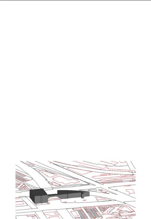
Figure 12.2 shows the implementation of the registration of 3D physical objects applied to the building complex in The Hague. The physical object in this figure represents the factual building. Also in this case, the z-values used to define the physical object are defined relative to the surface.
Figure 12.2: Registration of a 3D physical object.
Although the building crosses parcel boundaries, the whole building is registered as one object in the cadastral database. Separated from the parcels and outlines of
253

Chapter 12. Prototypes applied to case studies
buildings, the 3D physical object is maintained in a table containing the id of the object and the 3D geometry of the object (in this case defined as one multipolygon defined in 3D). The 3D object can be visualised and queried with a front-end in combination with 2D (preferably 2.5D) cadastral data. The legal status of the building is still registered by establishing rights on surface parcels. Consequently, the legal status of the building can only be obtained by examining the surface parcels. Since the 3D location of the building is integrated with the cadastral geographical data set, this information can be used in the querying process.
12.1.2Case study 2: The Hague Central Station
Generating 3D right-volumes
The process of automatically generating 3D right-volumes is described in this section using the case of The Hague Central Station.
For every parcel on which limited real rights or apartment rights are registered, a z-list is generated, that defines the upper and lower limits of (limited) rights (and apartment rights) established on the specific parcel. For example, in the case of The Hague Central Station, the vertical extents of the rights on the parcel that contains the tram and bus station and the railway platform are as follows (parcel 13295; see figure 12.3 (b)):
•railway platform (owned by NS Vastgoed): 0 to 6 m
•tram/bus station (right of superficies, holder municipality of The Hague): 6 m to 12 m.
Since the notarial deed gives no information about the boundaries of the established right of superficies for the bus/tram station in the third dimension, the levels were obtained by measuring the building (construction).
The z-list is inserted in the 3D right-volume table, as described in section 11.1.2. For The Hague Central Station the 3D right-volume table is as follows (implying fifteen 3D right-objects):
PARCEL Z LIST
12131 Z ARRAY(0, 12, 40)
13290 Z ARRAY(0, 12)
13288 Z ARRAY(0, 12)
13289 Z ARRAY(0, 12)
13294 Z ARRAY(0, 3, 12)
13291 Z ARRAY(0, 3, 12)
13293 Z ARRAY(0, 3, 12)
13292 Z ARRAY(0, 3, 12)
13295 Z ARRAY(0, 6, 12)
Non-spatial information on the 3D right-volumes (person who is entitled to the space; what right is established to entitle the person to the space) can also be obtained. In these first implementations the type of right and the person entitled to a 3D rightvolume (right-owner) are made available via views on the AKR base tables (‘right’ and ‘subject’). The list of owners and the list of types of right for every level are presented as arrays (Abstract Data Types) in the following view:
254