

3643
.pdfRussian Journal of Building Construction and Architecture
During transverse flowing of the round semi-cylinder there is an area of high liquid turbulization. On the plate there is a decrease in the thickness of the laminar sublayer of the liquid near the plate, which ultimately results in an increase in the heat energy transmission through this layer.
2. Practical importance, results of the experimental studies. An original structure of a shell-and-tube heat exchange tool was set forth with special heat exchange tubes fitted with the plates 2 with the cylindrically shaped ribs 3 in them [13]. This allows an increase in the heat exchange surface as well as extra turbulization of the flow of the heated liquid during flowing of the ribs (Fig. 3).
d
H 
 h
h

 D
D

 1
1
 2
2 


 3
3
l L
l
Fig. 3. Element of the heat exchange surface of the original shell-and-tube heat exchange tool: 1 is a tube, 2 is a plate, 3 are cylindrically shaped ribs
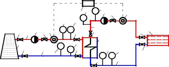
Based on the theoretical studies, a semi-industrial setup was designed as well as an intense shell-and-tube heat exchange tool (Fig. 4) [10].
The setup is divided into 2 contours:
I. The heating one: the heat energy source (11) – heat exchange tool (9) – heat supply source (11);
II. The heated one: heat exchange tool (9) – consumer (7) – heat exchange tool (9).
For the experiment a natural semi-industrial shell-and-tube heat exchange tool was used. The parameters of the tool are in Table 1.
40
Issue № 3 (43), 2019 |
ISSN 2542-0526 |
|
|
|
|
14 |
13 ТI |
5 2 |
3 |
|
4 |
|
|
|
13 |
5 |
РI |
|
|
|
|
|
|
РI ТI |
|
6 |
|
|
|
12 7 |
|
12 1 2 3 4 |
12 |
12 |
9 |
|
|
||||
11 |
|
|
|
5 |
|
|
|
|
|
|
РI |
|
|
|
|
|
|
||
12 |
10 |
ТI |
12 |
ТI |
5 |
13 |
12 |
||
|
|
13 |
|
|
|
РI |
8 |
|
|
|
|
|
|
|
12 |
|
|
||
Fig. 4. Independent heating system of a multi-storey residential building:
1 is a feeding pipe of the heat supply source; 2 is a circulation pump; 3 is a controlling tool; 4 is a flow meter; 5 is a thermometer; 6 is a feeding pipe from the heat exchange tool;
7 are consumers; 8 is a reverse pipe of the heating system; 9 is an intense shell-and-tube heat exchange tool; 10 is a reverse pipe to the heat supply source; 11 is a heat supply source; 12 is a switching-off tool;
13 is a manometer; 14 is a heat gauge
|
|
Таble 1 |
|
|
Parameters of the shell-and-tube heat exchange tool |
|
|
|
|
|
|
№ |
Parameter |
Value |
|
|
|
|
|
1 |
Tool length, m |
1 |
|
|
|
|
|
2 |
Diameter of the tool shell, mm |
32 × 2 |
|
|
|
|
|
3 |
Diameter of the heat exchange tube, mm |
10 × 1 |
|
|
|
|
|
4 |
Height of the plate, mm |
4 |
|
|
|
|
|
5 |
Diameter of the rib of the round section, mm |
4 |
|
|
|
|
|
6 |
Area of the section of the tube space, m2 |
0.00045 |
|
7 |
Number of ribs |
23 |
|
|
|
|
|
8 |
Threaded pipe joint |
3/4" |
|
|
|
|
|
The objective of the experiment is
––to study the heat transmission coefficient of the tool К, Watt/(m² °С) with the changed geometry of the heat exchange surface during seasonal variations in the average temperature pressure tср;
––to compare the heat transmission coefficients: that of the tool with the changed geometry
of the heat exchange surface and the serial tool.
41

Russian Journal of Building Construction and Architecture
The average temperature pressure according to the Guideline (СП) 41-101-95 “Designing Heat Spots” is given by the formula
tср |
(t1 t01) (t02 t2) |
, |
(4) |
||
|
|||||
|
2,3lg |
t1 t01 |
|
|
|
|
t02 t2 |
|
|||
|
|
|
|||
where t1 is the temperature of water in the feeding pipe of the heating contour (at the inlet of the tool), °С; t2 is the temperature of water in the reverse pipe of the heated contour (at the inlet of the tool), °С; t01 is the temperature of water in the feeding pipe of the heated contour (at the outlet of the tool), °С; t02 is the temperature of the water in the reverse pipe of the heating contour (at the outlet of the tool), °С.
It should be noted that the average temperature pressure is the main parameter for comparing two tools – the serial and examined one. The experiment was planned according to the temperature graphs of the heat energy source and consumer for low-temperature heat supply systems of the Belgorod region. In this area the start and end of the heating season corresponds with the average daily temperature of the outside air tнв +8 °С and the temperature of the outside air during the coldest five days (for designing heat supply systems) is –23 °С. Hence it is necessary to investigate the heat exchange tool at the temperatures in the feeding pipe of the heat supply source corresponding with tнв +8 and –23 °С as well as some intermediate tнв.
Based on the temperature graph of the heat energy source (95––70 °С at tнв= –23 °С) as well as that of the internal heating system (80––60 °С at tнв= –23 °С) the average temperature pressure for the serial tool is calculated and the liquid rate in this tool is also determined. The same hydraulic modes and temperature pressures are employed for investigating the shell- and-tube heat exchange tool with the changed geometry of the heat exchange surface. The cross direction of the heat carrier flows in the heated and heating contours were chosen as the most effective one for the heat supply systems [5]. Therefore the experiment plan was designed (Table 2).
|
|
|
|
|
|
|
Таble 2 |
Experiment plan for the semi-industrial setup |
|
|
|
||||
|
|
|
|
|
|
|
|
Temperature of the outside air, tнв, °С |
–17 |
–15 |
–10 |
–5 |
0 |
+5 |
+8 |
|
|
|
|
|
|
|
|
Теmperature t1, °С |
85 |
82.3 |
74.1 |
65.6 |
56.9 |
47.7 |
43.0 |
|
|
|
|
|
|
|
|
Average temperature pressure tср, °С |
11.0 |
9.72 |
7.97 |
6.12 |
4.25 |
3.11 |
2.24 |
|
|
|
|
|
|
|
|
Liquid rate in the tool tube, m/seс |
|
|
|
1.23 |
|
|
|
|
|
|
|
|
|
|
|
Liquid rate in the tube space, m/sec |
|
|
|
0.16 |
|
|
|
|
|
|
|
|
|
|
|
42
Issue № 3 (43), 2019 |
ISSN 2542-0526 |
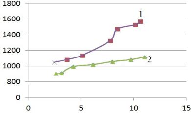
The results of the experiment are in the graph (Fig. 5).
transmissi, |
С) |
Coefficient of heat |
Watt/(m² ° |
Average temperature pressure, ° С
Fig. 5. Graph of the dependence of the heat transmission coefficient on the temperature pressure: 1 of the shell-and-tube heat exchange tool with the changed geometry of the heat exchange surface; 2 of the tool according to the GOST (ГОСТ) 27590-2005
The graph shows that the heat transmission coefficient К, Watt/(m² °С) increases as does the average temperature pressure and is on average 20 % larger than that of the serial heat exchange manufactured according to the GOST (ГОСТ) 27590-2005.
Conclusions. As part of the experimental studies, it was proved that turbulization of the heated liquid in the shell-and-tube tool [13] with the cylindrically shaped rib causes intensification of heat exchange. An increase in the heat transmission coefficient during a seasonal increase in the temperature pressure (the lower is the temperature of the outside air, the higher is the temperature pressure) is more intense in the investigated tool (Fig. 5) than in the serial one (GOST (ГОСТ) 27590-2005). A large heat transfer coefficient К, Watt/(m² °К), ultimately results in a reduction in the standard size of a heat exchange tool.
The operation of a highly effective shell-and-tube tool with the changed geometry of the heat exchange surface is believed to enable one to take advantage of the lamellar tool (high turbulization) as well as to raise the reliability of heat supply systems and simplify as and cut down current and routine maintenance costs.
References
1. Alkhasova D. A. ["Mukhtar's readings": The increase in heat transfer between the flows of ribbing partition].
Trudy "Mukhtarovskie chteniya": Sovremennye problemy matematiki i smezhnye voprosy" [Proc. "Mukhtar Readings": Modern problems of mathematics and related issues"]. Makhachkala, 2008, pp. 31—34.
43

Russian Journal of Building Construction and Architecture
2.Bazhan P. I., Sorokin O. G. Podogrevateli VVPI –– dostoinstva, nedostatki, metodika predvaritel'nogo podbora [Heaters VVPI – advantages, disadvantages, methods of pre-selection]. Novosti teplosnabzheniya, 2006, no. 3, pp. 39––47.
3.Bashmakov I. A. Analiz osnovnykh tendentsii razvitiya sistem teplosnabzheniya Rossii [Analysis of the main trends in the development of heat supply systems in Russia]. Novosti teplosnabzheniya, 2008, no. 90, pp. 51––58.
4.Buglaev V. T., Anisin A. A. Vliyanie geometricheskikh parametrov sferoidal'nykh elementov rel'efa i skhemy ikh raspolozheniya na teplovuyu effektivnost' plastinchatoi poverkhnosti teploobmena [Influence of geometrical parameters of spheroidal relief elements and their arrangement scheme on thermal efficiency of plate heat exchange surface]. Izvestiya vuzov. Yadernaya energetika, 2002, no. 3, pp. 39––49.
5.Zhukauskas A. A. Konvektivnyi perenos v teploobmennikakh [Convective transfer in heat exchangers]. Moscow, Nauka Publ., 1982. 472 p.
6.Kruglov G. A., Bakunin V. V., Andreeva M. V. Teoreticheskie issledovaniya stepeni vzaimosvyazi turbulizatsii potoka s koeffitsientom teplootdachi [Theoretical studies of the degree of relationship between the flow turbulence and the heat transfer coefficient]. Vestnik KrasGASU, 2015, no. 6, pp. 67––73.
7.Kuntysh V. B., Sukhotskii A. B., Yatsevich A. V. Teplovaya effektivnost' vikhrevoi intensifikatsii teplootdachi gazovogo potoka pri prodol'nom i poperechnom obtekanii kruglotrubnykh poverkhnostei [Thermal efficiency of vortex intensification of gas flow heat transfer at longitudinal and transverse flow around round-tube surfaces]. Izvestiya vysshikh uchebnykh zavedenii SNG, 2014, no. 2, pp. 68––75.
8.Kucherenko D. I. Ochistka vodopodogrevatelei sistem goryachego vodosnabzheniya i otopleniya [Cleaning of water heaters of hot water supply and heating systems]. Novosti teplosnabzheniya, 2004, no. 2, pp. 56––60.
9.Kushchev L. A., Nikulin N. Yu., Ovsyannikov Yu. G. [The use of heat exchangers in the systems of housing and communal services of the Belgorod region]. Trudy "Nauchno-tekhnicheskie problemy sovershenstvovaniya i razvitiya sistem gazoenergosnabzheniya" [Proc. "Scientific and technical problems of improvement and development of gas and energy supply systems"]. Saratov, 2018, pp. 111––116.
10.Kushchev L. A., Nikulin N. Yu., Alifanova A. I. Sovremennye metody intensifikatsii teploobmena v kozhukhotrubnykh teploobmennykh apparatakh ZhKKh [Modern methods of heat exchange intensification in shell-and-tube heat exchangers of housing and communal services]. Vestnik BGTU im. V. G. Shukhova, 2017, no. 9, pp. 73––79.
11.Nekrasov A. S., Sinyak Yu. V., Voronina S. A. Perspektivy razvitiya teplosnabzheniya Rossii [Prospects for the development of a heat supply of Russia]. Novosti teplosnabzheniya, 2011, no. 128, pp. 125––131.
12.Olesevich K. A., Olesevich A. K., Osipov M. I. Eksperimental'noe issledovanie teplogidravlicheskikh kharakteristik kozhukhotrubnogo teploobmennogo apparata s vintovoi peregorodkoi [Experimental study of thermohydraulic characteristics of a shell-and-tube heat exchanger with a screw partition]. Vestnik Moskovskogo gosudarstvennogo tekhnicheskogo universiteta im. N. E. Baumana, 2004, no. 2, pp. 262––265.
13.Nikulin N. Yu., Kushchev L. A., Suslov D. Yu. e. a. Kozhukhotrubyi teploobmennyi apparat [Shell and tube heat exchanger]. Patent RF, no. 2014134083/06, 2015. 12 p.
14.Statistika [Statistics]. Ministerstvo energetiki RF: ofitsial. sait. Available at: https://minenergo.gov.ru/activity/statistic.
15.Shlikhting G. Teoriya pogranichnogo sloya [The theory of the boundary layer]. Moscow, Nauka Publ., 1974. 712 p.
44
Issue № 3 (43), 2019 |
ISSN 2542-0526 |
16.Jin M., Liu H. J., Wang X. Y. Optimization research of sextant fan baffle curvature radius in shell and tube heat exchanger, 2017, vol. 231, pp. 1––6. Available at: https://www.researchgate.net/publication/319888046_Optimization_research_of_sextant_fan_baffle_curvature_radius_in_shell_and_tube_heat_exchanger.
17.Kushchev L. A., Nikulin N. Yu., Alifanova A. I. Intensity enhancement of heat exchange in shell-tube heat exchangers with smooth pipes. Advances in Engineering Research, 2017, vol. 133, pp. 390––395.
18.Luben C. G., Hẻlio A. N., Josẻ M. S. Thermal Performance Modeling of Cross-Flow Heat Exchangers. German, Springer, 2015. 226 р.
19.Malhotra A., Muhaddin S. Modeling and computation for designs of multistage heat exchangers systems. Math. Comput. Modelling, 1990, vol. 14, pp. 826––831.
20.Mića V., Mladen A., Predrag M. Effect of segmental baffles on the shell-and-tube heat exchanger effectiveness. Hemijska industrija, 2014, vol. 68 (2), pp. 171––177. doi: 10.2298/HEMIND130127041V.
45

Russian Journal of Building Construction and Architecture
BUILDING MATERIALS AND PRODUCTS
DOI10.25987/VSTU.2019.3.43.004
UDC691.327
S. I. Pimenov1
FEATURES OF THE STRUCTURE FORMATION OF A CEMENT STONE AFTER HYDRO-MECHANOCHEMICAL ACTIVATION OF CEMENT
Kazan State University of Architecture and Engineering1
Russia, Kazan
1PhD in Engineering, Reader of the Dept. of Building Production, tel.: +7-843-510-47-31, e-mail: 3.14manon@mail.ru
Statement of the problem. Improving the quality of building materials at lower energy and resource costs remains an urgent issue. As warped rotors are developed, cement slurry is capable of activating inside them. Up until recently, the technology of concrete involving activation of cement and water slurry in warped rotors has failed to become common as there are scientific and technical issues yet to be tackled.
Results. The results of the influence of hydromechanochemical activation of a cement slurry on the physical and technical properties of heavy concrete are presented in the article. The dispersed composition of cement powder obtained after hydromechanochemical activation of the binder is presented. The index of the structure of heavy concrete structure, frost resistance, coefficient of sulfate resistance of the investigated concrete composition s has been identified. A high growth rate of the cement composition s is due to a high heat transfer of the cement stone at the beginning of the formation of the structure. The X-ray phase analysis showed that the phase composition of cement stone obtained after the mechanical and chemical activation of the binder is characterized by an increased amount of hydration growth.
Conclusions. The production of fast hardening cement concrete would reduce its holding time of the concrete in the formwork as well as reduce or eliminate heat treatment, which is relevant in terms of efficient use of energy and resources.
Keywords: hydromechanochemical activation, superplasticizer Relamix T-2, cement slurry, frost resistance.
Introduction. Portland cement capacities in improving chemical activity seem to be exhausted, but there is still some potential to de discovered in activating minerals that change hydratation processes [2, 5, 7, 11, 16, 17].
© Pimenov S. I., 2019
46
Issue № 3 (43), 2019 |
ISSN 2542-0526 |
The most common cement activation methods are turbulence [20, 25, 35], cavitation [1, 36], mechanochemical and hydromechanochemical [6, 16, 24, 26, 27, 30, 32, 33, 38], ultrasound [23, 31], vibration [3, 15], etc. All of the above activation methods are designed to improve the dispersion and specific surface of cement aggregate particles and hydrate growth. However, as the same dispersion of hydrate growth in different ground tools is reached, physical and technical properties of cement composition s might vary [40]. When Portland cement is ground using various tools, its components are significantly affected, i. e. the way a grid destroys as well as particle aggregation change. Energy consumption for dispersion of a binder using various tools for achieving the same effect is also different. The energy consumption for fine cement grounding in a water environment was proved to be lower than in a dry form on the condition that the same dispersion is achieved [10, 14]. Therefore it would be viable to make use of the equipment for dispersion of cement and water slurry that has a high energy consumption and intensity with a high power and hydrodynamic resistance particularly when effective modifying supplements are employed.
Cement hydromechanoactivation. A variety of technological methods of dispersion and activation of cement composition s is currently employed. After pulsed rotary equipment (PRE) had been designed, cement slurry could be activated there [7]. Up until recently the technology involving activation of a cement and water slurry in PRE has not become common due to a few scientific and technical issues yet to be resolved.
The authors in [12, 20] argue that mechanoactivation of cement and water slurry at the outset of hydration and hardening contribute to an increase in the volume of chemically active coagulation environment and its compaction, which leads to an increase in the strength of up to 30 %. In [37, 39] it is noted that due to the activation of cement slurry in PRE the strength of a cement and sand solution goes up by 70 %.
The dispersion of binders as they are processed in a planetary-type mill for 25 min was found to reach 650 m2/kg while in a ball grinder the same level of dispersion is achieved only for 120 min [28]. An increase in the specific surface of a binder causes an increase in the physical and technical properties of cement composition s but only as high as 500––600 m2/kg. An increase in the specific surface of cement particles causes a sharper decrease in its activation [16, 34]. In order to prevent cement activation as it is stored from decreasing, a binder should be activated in a water environment.
The strength of cement composition s is known to decrease as the amount of water of binder mixing increases, which is due to a growing porous structure of a cement stone [24, 30, 32].
47

Russian Journal of Building Construction and Architecture
In order to prevent this, effective superplasticizers as well as binders have to be mechanically processed with no modifying supplements [4, 12, 20, 28, 37, 39].
Hydromechanochemical activation of a modified binder. Dispersion of a binder in a water environment can be intensified due to extra surfactants, i. e. superplasticizers.
Scientists discovered an intensifying effect of surfactants on cement grinding. Introduction of a few supplements into fine grinding contributes to more effective grinding as well as improved physical and mechanical properties of resulting cement composition s.
A list of available superplasticizers is constantly growing and it is becoming increasingly difficult to choose an effective surfactant for the dispersion of a binder in various tools.
There is no data available in the literature on the effect of hydromechanical chemical activation of a cement slurry in PRE on the kinetics of heat emission of a cement paste, as well as of granulometric composition of a cement powder following activation, the structure of heavy cement on hydromechanochemically activated cement.
In the previous study [8] it was found that for manufacturing assembled ferroconcrete products preliminary hydromechanochemical activation of a cement slurry allows energy consumption to decrease and the cost of 1 cubic meter of a ready product to be reduced down to 24 % if it is not used whatsoever. Therefore the objective of the research is to analyze the results of the effect of hydromechanochemical activation of a cement slurry on the kinetics of hardening and physical and technical properties of heavy cement, cement hydration by means of the X-ray phase analysis method.
1. Materials and equipment. For manufacturing a concrete mix the following original materials were used:
––Portland slag cement ЦЕМ II/A-Ш 32.5H by the Yulianovsk Plant in compliance with the GOST (ГОСТ) 31108-2016 requirements. It contains the following main minerals: C3S – 54 %, C2S – 20 %, C3A – 11 %, C4AF – 12 %, 9.2 % of a mineral supplement of granulated burnt furnace slag, 2.8 % of SO3 impurity. The choice of a medium-scale Portland cement was due to its high efficiency during mechanochemical activation in a water environment and the use of a granulated burnt furnace slag as a mineral supplement saved some amount of an aggregate and provided environmental sustainability as well as its positive impact on the structure formation of a cement stone following activation and interaction with calcium hydroxide resulting in predominantly strong low-base calcium hydrosilicates;
––sand of the Kamsko-Ustiynskiy deposit with the fineness modulus of 2.7 was used as a fine filler and was in compliance with the GOST (ГОСТ) 8736-2014;
48
Issue № 3 (43), 2019 |
ISSN 2542-0526 |
––loam of the Ural deposit with the fraction sized 5––20 mm was used as a fine filler and was in compliance with the GOST (ГОСТ) 8267-93;
––naphthalene formaldehyde superplasticizer was used as a superplasticizer supplement Relamix T-2 manufactured by ТУ 5870-002-14153664-04 in the amount of 1 % of the cement mass. The use of superplasticizer supplements for enhancing previous strength and physical and mechanical properties of heavy concrete is beyond any doubt as it provides a considerable (up to 30––40 %) reduction in the water consumption necessary for producing high strength cement.
Heavy concrete В25 was prepared and tested with the ratio of the components in the following proportions: cement : sand : loam = 490 : 555 : 1315.
The cement-water ratio (W/C) of the investigated compositions was chosen on the condition that the same mobility of the П2 brand is achieved (the cone heaving was 6––8 cm according to the GOST (ГОСТ) 10181-2014). This mobility of the concrete mix was chosen in compliance with the requirements for manufacturing different concrete and ferroconcrete products (slabs, beams, columns, straps, etc.) according to the Construction Guidelines and Regulations (СНиП) 3.09.01-85 “Manufacturing Assembly Ferroconcrete Structures and Products”.
The cement was subjected to hydromechanochemical activation in pulsed rotary equipment manufactured by Ltd. Promservice according to the Technical Specifications (ТУ) 5132-001- 70447062.
The specific surface was determined by means of the air permeability method on a tool for measuring the specific surface area (ПСХ-9). The dispersion composition was identified using a laser diffraction particle size analyzer Horiba La-950V2.
The X-ray phase analysis was conducted on using the diffractometer D2 Phaser (Bruker, Germany) for measuring powder diffraction in Bragg-Brentano geometry using a monochro-
matic CuK -radiation (λ = 1.54178 Ǻ) in the continuous scanning mode.
The measurement and reading modes were the following: the strain of the X-ray tube was 30 kW, the current was 30 mА, scanning step and rate was 0.02° and 1 degrees/min respectively. A range of scanning angles in Bragg-Brentano geometry was 3––60°.
2. Меthods. Cement and aggregate materials that are active in water environment and obtained following PRE treatment were dehydrated using a Buchner funnel that was joined to a water flow pipe. Once the liquid phase was separated, a sample on the filter was poured with pure alcohol and preserved in acetone. The amount of acetone was one-fifth of the sample. After that the sample was dried in a drying chamber at the temperature 105 °С.
49