

3643
.pdfRussian Journal of Building Construction and Architecture
does the pressure increase at the moment respectively. This is completely in agreement with the criterion of use of maximum light moving parts in structures of shock nodes to reach their maximum efficiency and reliability as specified in [6, p. 67].
A(1,2jΩ)
1
0,8
0,6
0,4
0,2
0
0 |
2 |
|
4m1 |
6 m2 |
8 |
m3 |
10 |
Ω, rad12/sec |
|
|
|||||||||
|
|
|
|
|
|||||
|
|
|
|
|
|
Fig. 9. Amplitude and frequency characteristics of the shock node when the valve closes depending on changes in the mass of its moving parts: т1 < т2 < т3, т2 is the basic parameter
A(1,2jΩ)
1
0,8
0,6
0,4
0,2
0
0 |
2 |
4 |
l1 |
6l2 |
l38 |
10 |
Ω, rad/12sec |
|
|
|
|||||||
Fig. 10. Amplitude and frequency characteristics of the shock node when the valve closes depending on changes in the deformation of its moving parts: l1 < l2 < l3, l2 is the basic parameter
30
Issue № 3 (43), 2019 |
ISSN 2542-0526 |
Fig. 10 suggests that as the deformation (a decrease in the rigidity) of the elements of the shock node increase, its maximum efficiency is reached at lower valve switching frequencies. Conversely, an increase in the rigidity of a structure causes a shift in the effective frequency of the generation of the impulses of the hydraulic shock and increases it.
A1,2(jΩ)
1
0,8
0,6
0,4
0,2
0
0 |
2 |
4 |
|
6 |
8 |
10 |
12 |
|
|
|
|
|
V1 |
V2 |
V3 |
|
Ω, rad/sec |
|
|
|
|
|
|
|||
Fig. 11. Amplitude and frequency characteristics of the shock node when the valve closes depending on changes in the consumption of the operating environment: V1 < V2 < V3, V2 is the basic parameter
A(jΩ)2
1,8
1,6
1,4
1,2
1
0,8
0,6
0,4
0,2
0
0 |
2 |
4 |
6 |
8 |
10 |
12 |
|
|
|
|
r2_1 |
r2_2 |
r2_3 |
|
Ω, rad/sec |
|
|
|
|
|
|||
Fig. 12. Amplitude and frequency characteristics of the shock node when the valve closes depending on changes in the mechanical (active) resistance of the valve:: r2_1 < r2_2 < r2_3, r2_2 – are the basic parameters
31

Russian Journal of Building Construction and Architecture
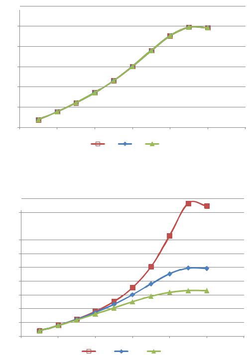
Fig. 11 suggests that changes in the consumption of the operating environment when the other basic parameters of the system are stable have no influence on the choice of an optimal frequency of the generation of hydraulic shocks. For the chosen construction solution for the setup the most effective frequency is within 1.5 Hz. When the valves of the shock node are externally operated, this describes its stable operation as the consumption of the operating environment changes unlike a self-powered structure of the valve where the consumption of the operating environment defines its switching frequency and a relatively small range of the operation frequency [4].
Fig. 12 shows that active mechanical resistance of the valve is directly proportionate to the closing rate change of the valve v, m/seс.
Conclusions. Through the course of the study a technical solution for the shock node of the opposite structure was obtained making it possible to externally operate its valves, which allows the impulses of the amount of movement in the operating environment to be generated with the specified frequency and amplitude independent of its consumption. The novelty of the proposed structure is proved by the Russian Federation patent [8].
The results of the experimental study of the operation of the above shock node with the standard size G3/2 are indicative of its productivity at the valve switching frequency from 0.1 to 2.5 Hz in the range of changes in the consumption of the operating environment 0.176–– 2.241 m3/h (2.94––37.35 l/min). As the consumption drops below that, hydraulic shock is not generated and as the consumption increases, the network pump operates in the emergency mode with an overcurrent as a result of an extreme hydraulic resistance of the shock node. The latter is also accompanied by depressurization of compacting materials and failure of some elements of the structure of the shock node itself and the hydraulic contour as a result of the impact of a powerful hydraulic shock.
The experimentally obtained graphs of pressure changes at the moment of the hydraulic shock allow a maximum pressure growth to be predicted at the moment of the hydraulic shock for a certain hydraulic system. E. g., if the permissible pressure for a heat supply system is 1000 kPа, there should be no increase of over 25 l/min in the consumption of the operating environment through the shock node of a structure with the standard size G3/2 . Besides, for each hydraulic system some maximum increase in the pressure in the impulse of the hydraulic shock depending on the frequency of valve switching should be taken into consideration.
The results of the mathematical modeling show that all the parameters of the energy chain except active hydraulic resistance of the valve and consumption of the operating environment have a significant influence on the character of the generation of the hydraulic shock by
32
Issue № 3 (43), 2019 |
ISSN 2542-0526 |
means of the shock node. An increase in the mass of the moving parts causes a decrease in the maximum amplitude and frequency characteristics and its shift to a lower angular speed. An increase in the deformation (a decrease in the rigidity of the reverse valve spring) also causes a shift in the maximum amplitude and frequency characteristics into lower frequencies but with no changes in the amplitude. What is typical of mechanical systems is that as active mechanical resistance of the valve drops, there is a sharp increase in the amplitude.
Therefore it can be stated that the suggested structure of the operated shock node allows the impulses of the amount of movement of the operating environment to be generated with a necessary frequency and amplitude of a pressure increase at the moment of a hydraulic shock in a relatively wide range of changes in the consumption of the operating environment. Hence the resulting technical solution can be applied for extending the potential of impulse and pulsing circulation of a heat carrier in the context of intensifying heat exchange, transformation of available head pressure from one hydraulic contour into another and self-purification of heat-transmitting surfaces in heat supply systems of the above values and quantitative indices obtained using self-powered shock nodes. The detailed data will be presented in the follow-up papers.
References
1.Galitseiskii B. M., Ryzhov Yu. A., Yakush E. V. Teplovye i gidrodinamicheskie protsessy v koleblyushchikhsya potokakh [Thermal and hydrodynamic processes in oscillating flows]. Moscow, Mashinostroenie Publ., 1977. 256 p.
2.Levtsev A. P., Makeev A. N. Impul'snye sistemy teplo- i vodosnabzheniya [Impulse systems of heat and water supply]. Saransk, Izd-vo Mordov. un-ta, 2015. 172 p.
3.Makeev A. N. Impul'snaya sistema teplosnabzheniya obshchestvennogo zdaniya. Avtoref. diss. kand. tekhn. nauk [Impulse heat supply system of public building. Dr. eng. sci. diss.]. Penza, 2010. 20 p.
4.Makeev A. N. Issledovanie kharakteristik udarnogo uzla samopodderzhivayushcheisya oppozitnoi konstruktsii [Study of the characteristics of the impact unit of self-supporting opposition structure]. Promyshlennaya energetika, 2018, no. 3, pp. 32––37.
5.Makeev A. N. K voprosu lokal'noi organizatsii impul'sno-koleblyushcheisya tsirkulyatsii teplonositelya v sisteme teplosnabzheniya [To the question of local organization of pulse-oscillating circulation of coolant in the heat supply system]. Byulleten' nauki i praktiki. Nizhnevartovsk, 2018, vol. 4, no. 5, pp. 254––262.
6.Ovsepyan V. M. Gidravlicheskii taran i tarannye ustanovki [The hydraulic RAM and RAM setup]. Moscow, Mashinostroenie Publ., 1968. 124 p.
7.Levtsev A. P., Makeev A. N., Makeev S. N., Khramov S. I., Narvatov Ya. A. Teplovoi punkt [Heat point]. Patent RF, no. 2013137717/12, 2015.
8.Levtsev A. P., Makeev A. N., Golyanin A. A. Udarnyi uzel [Shock node]. Patent RF, no. 2018112914, 2018.
33

Russian Journal of Building Construction and Architecture
9.Levtsev A. P., Makeev A. N., Lazarev A. A. Avtonomnaya sistema otopleniya dlya zdaniya avtonomnogo pol'zovaniya [Autonomousheating systemfor thebuilding of Autonomoususe].PatentRF,no.2009113871/22,2009.
10.Rostovtsev V. N. Utylyzacija malыhъ padenij vodы dlja celej osushenija y oroshenija zemel' [Disposal of small drops of water for drainage and irrigation purposes]. Petrograd, 1916. 48 p.
11.Akcay S., Akdag U. Parametric investigation of effect on heat transfer of pulsating flow of nanofluids in a tube using circular rings. Amukkale university journal of engineering sciences-pamukkale universitesi muhendislik bilimleri dergisi, 2018, vol. 24, iss. 4, pp. 597––604. doi: 10.5505/pajes.2017.70120.
12.Ali S., Habchi Ch., Menanteau S., Lemenand T., Harion J.-L. Heat transfer and mixing enhancement by free
elastic flaps oscillation. International Journal of Heat and Mass Transfer, 2015, vol. 85, pp. 250––264. doi: 10.1016/j.ijheatmasstransfer.2015.01.122.
13.Butun H., Kantor I., Marechal F. A heat integration method with multiple heat exchange interfaces. ENERGY: 30th International Conference on Efficiency, Cost, Optimisation, Simulation and Environmental Impact of Energy Systems (ECOS), 2018, vol. 152, pp. 476––488. doi: 10.1016/j.energy.2018.03.114; WOS: 000432760200042.
14.Chang S. W., Su L. M., Hwang C. C., Yang T. L. Heat transfer in a reciprocating duct fitted with transverse ribs. Experimental heat transfer, 1999, vol. 12, iss. 2, pp. 95––115. doi: 10.1080/089161599269735.
15.Désidéri J.-A., Duvigneau R. Parametric optimization of pulsating jets in unsteady flow by multiple-gradient descent algorithm (MGDA). Computational Methods in Applied Sciences, 2019, vol. 47, pp. 151––169. doi: 10.1007/978-3-319-78325-3_11.
16.Dushin N. S., Mikheev N. I., Paereliy A. A., Gazizov I. M., Shakirov R. R. Kinematics of pulsating flow in the entry region of the channel with discrete roughness elements. Journal of Physics: Conference Series, 2017, vol. 891, iss. 1. doi: 10.1088/1742-6596/891/1/012147.
17.Kærn M. R., Elmegaard B., Meyer K. E., Palm B., Holst J. Continuous versus pulsating flow boiling. Experimental comparison, visualization, and statistical analysis. Science and Technology for the Built Environment, 2017, vol. 23, iss. 6, pp. 983––996. doi: 10.1080/23744731.2017.1319667.
18.Levtzev A. P., Makeev A. N., Kudashev S. F. Pulsating heat transfer enhancement in the liquid cooling system of power semiconductor converter. Indian Journal of Science and Technology, 2016, vol. 9 (11). doi: 10.17485/ijst/2016/v9i11/89420.
19.Makeev А. N. Implementation of pulse heat supply for dependent connection of customers = Obespechenie impul'snogo teplosnabzheniya dlya zavisimogo prisoedineniya abonentov. Magazine of Civil Engineering = Inzhenerno-stroitel'nyi zhurnal, 2018, no. 07 (83), pp. 114––125. doi: 10.18720/MCE.83.11.
20.Makeev А. N. Theory of pulse circulation of the heater in the heat supply system with independent subscription of subscribers. Russian journal of building construction and architecture, 2018, no. 4 (40), pp. 15––25. wos: 000450361700002.
21.Seo Y. K., Byung H. K., Jae M. H. Heat transfer in the thermally developing region of a pulsating chan-
nel flow. International Journal of Heat and Mass Transfer, 1993, vol. 36, iss. 17, pp. 4257––4266. doi: 10.1016/0017-9310(93)90088-N.
22.Sundstrom L. R. J., Cervantes M. J. On the Similarity of Pulsating and Accelerating Turbulent Pipe Flows. Flow turbulence and combustion, 2018, vol. 100, iss. 2, pp. 417––436. doi: 10.1007/s10494-017-9855-5.
23.Valueva E. P., Purdin M. S. Heat exchange at laminar flow in rectangular channels. Thermophysics and aeromechanics, 2016, vol. 23, iss. 6, pp. 857––867. doi: 10.1134/S0869864316060081.
34

Issue № 3 (43), 2019 |
ISSN 2542-0526 |
DOI10.25987/VSTU.2019.3.43.003
UDC 697:620.9(07)
L. А. Kuschev1, N. Yu. Nikulin2, А. Yu. Feoktistov3
HIGHLY EFFICIENT SHELL-AND-TUBE HEAT EXCHANGERS
FOR COMMUNAL HOUSEHOLD SYSTEMS
Belgorod State Technological University Named after V.G. Shukhov1, 2, 3
Russia, Belgorod
1D. Sc. in Engineering, Prof. of the Dept. of Heat and Gas Supply and Ventilation, tel.: (4722)55-94-38, e-mail: Nick_973gt@mail.ru
2PhD student of the Dept. of Heat and Gas Supply and Ventilation, tel.: +7-908-788-8313, e-mail: Nick_973gt@mail.ru
3PhD in Engineering, Assoc. Prof. of the Dept. of Heat and Gas Supply and Ventilation, tel.: (4722)55-94-38, e-mail: Nick_973gt@mail.ru
Statement of the problem. Heat and gas supply equipment (heat networks and boiler rooms) in the Russian Federation is generally worn-out. An important element of the heat and gas supply system is shell-and-tube and lamellar heat exchangers that are employed in thermal electric stations and atomic electric stations, boiler rooms, etc. The use of these tools is a more viable engineering solution than lamellar ones due to a number of operational and economic factors. The methods of enhancing heat exchange of shell-and-tube tools are discussed.
Results and conclusions. It was found that the most promising method of enhancing heat exchange is to change the geometry of a heat exchanger surface: longitudinally ribbed heat exchanger tubes, tubes with a hole on the outside surface, etc. The theoretical aspects of increasing heat emission of the heated solid surface using liquid turbulization. An original structure of the shell- and-tube heat exchanger with special heat exchange tubes fitted with plates with cylindrical ribs. According to the natural experiment, the heat exchange coefficient of the resulting shell-and-tube heat exchanger with the modified geometry of the heat exchanger surface and on average 20 % higher turbulization than that of the mass production one.
Keywords: heat exchanger, turbulization, heat exchanger surface, heat exchange coefficient.
Introduction. The heat supply system of the Russian Federation is the largest in the world
with the heat energy consumption of around 35 % of the total one [3].
The article was prepared as part of the federal development program of the Branch University with the support from the Belgorod State Technological University Named after V.G. Shukhov: N A-35/17 "Intensification of Heat Exchange in Shell-and-Tube Heat Supply Systems of Communal Households" from 24.07.17.
© Kuschev L. А., Nikulin N. Yu., Feoktistov А. Yu., 2019
35
Russian Journal of Building Construction and Architecture
However, these days a heat supply system is faced with technological challenges during production, transfer and distribution of heat energy: the proportion of boiler rooms with completely worn out equipment is around 60 %, the average percentage of worn out thermal and steam networks is estimated at 60––70 %, worn out equipment in heat supply system is reported to be 60 %.
In the Russian Federation the communal household system is one of the most crucial industries in the public sector. Reconstruction as well as construction of new residential homes, energy modernization of the country’s heat supply infrastructure is a top priority in the social policy. The annual proportion of residential construction is about 2 % of the housing fund [11].
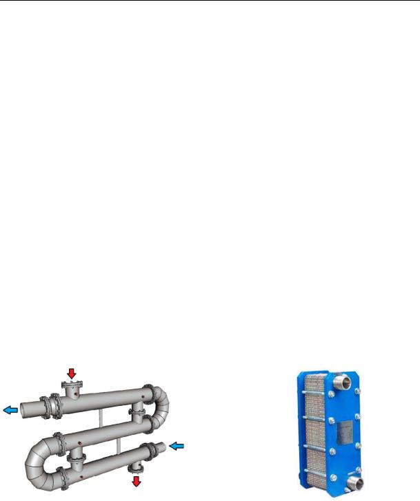
A significant part of the Russian Federation is located in sharply and moderately continental climate zones. The heating season might last from 72 to 365 days. In order to create favourable work and leisure conditions heat supply systems are employed. Currently over 500 large heat energy sources are being employed in the Russian Federation (atomic power plants, thermal electric power plants, boiler rooms with the power capacity of over 58 MWatt) [17]. In the calendar year of 2017 according to the data from the Ministry of Energy, the Russian Federation produced 4,94 108 Gcal of thermal energy, which is 13 % more than in the previous year [14]. The main type of heat exchange equipment for thermal energy production is shell-and-tube and lamellar heat exchange tools (Fig. 1). This equipment is employed in thermal electric power plants and atomic power plants, boiler rooms, central and individual thermal spots.
-
а) |
b) |
Fig. 1. Shell-and-tube (а) and lamellar (b) heat exchange tools
The use of lamellar heat exchangers is associated with operation and maintenance challenges. First of all, heat exchange surfaces experience skulling. A limescale layer with the thickness 0.3 mm causes a 2.5 time decrease in the heat transfer coefficient compared to the calculation data [2, 8]. A scaling inhibitor, i.e. oxyethylidenediphosphonic acid, can be added into a hot water supply system in order to prevent skulling [9].
36
Issue № 3 (43), 2019 |
ISSN 2542-0526 |
Heat exchanger plates should be disassembled or assembled by a team of no less than 2 professionals with use of special equipment. Rubber gaskets (EPDM material) of a complex shape are damaged which require replacement if a tool is frequently (3 or more times) disassembled. The cost of gaskets should be 30––70 % of that of a new tool with actual service life of rubber gaskets of around 3––5 years. Therefore EPDM-compactions have to be replaced 1––2 times after 5 years of operation.
Traditionally in heat supply systems in the Russian Federation shell-and-tube heat exchange tools are more widely used which typically have a relatively low hydraulic resistance and can use operating environments with various aggregate states (steam in the heating contour, water in the heated one and the other way round). These tools can operate on water with extreme rigidity (over 700 mkg-equiv/l), temperature (up to 550°) and high pressure (up to 14 МPа). It should be noted that for shell-and-tube heat exchangers the skulling thickness of 0.3 mm only causes a 10 % reduction in the heat transfer coefficient.
Hence for analysis of the positive and negative aspects of heat exchange tools, intensification of heat exchange in shell-and-tube tools for increasing their productivity is of particular importance.
1. Theoretical foundation of intensification of heat exchange in the geometry of a heat exchange surface. The Russian Federation as well as other countries is engaged in studies of intensification of heat exchange in shell-and-tube heat exchange tools.
Intensification of heat exchange is discussed in the paper by D. A. Alkhasova [1]. The efficiency of the method of longitudinal ribbing of a heat exchange tube was investigated and a 4––5 time increase in the heat flow was achieved compared to a bare surface. However, as the number of longitudinal ribs raises so does the hydraulic resistance.
In [12] there is a discussion of a shell-and-tube heat exchange tool where a block of regular support partitions (perpendicular to the tool axis) was replaced by a screw one. This contributes to a 1.4 time increase in heat exchange compared to a serial tool manufactured in accordance with the GOST (ГОСТ) 24590-2005. It is also essential to account for challenges associated with manufacturing the tool as well as a relatively high hydraulic resistance at high rates of the operating environment in tube space.
In the papers by G. А. Kruglov and V. V. Bakunin [6] it is suggested that a smooth pipe is used which is bent like a spiral to increase heat emission from a heating heat carrier to a wall pipe by 1.5 times.
Specialists in the Belarus State Technological University [7] conducted a series of experimental studies on longitudinal flowing by a heat exchange pipe with notches on the outside
37

Russian Journal of Building Construction and Architecture
surface. This enabled heat exchange to increase by 1.39 times with heat emission dropping dramatically as the notches experienced skulling.
In a lot of countries (USA, Canada, Great Britain, Germany, France, India, China, Iraq) there has been ongoing research effort to investigate the efficiency of shell-and-tube heat exchange tools [18, 19]. Original technical solutions for improving turbulization of a liquid flow at the heated as well as cooled surface (in the heating and heated contour).
Chinese specialists M. Jin, H. Liu, K. Wang performed a study of a shell-and-tube heat exchange tool with smooth pipes and modernized partitions which were a circle with alternating 60° sectors [16]. The sector angle was also 60 °. The goal of the experiment was to investigate a coefficient of heat exchange and hydraulic resistance. According to the results, the heat coefficient using such partitions could be increase by 6,8 % (compared to regular partitions). A drawback of this technical solution is challenging manufacturing of the tool.
In Iran Ashkan Alimoradi developed and examined a shell-and-tube heat exchange tool with spiral heat exchange pipes. A heat exchange pipe was found to emit more heat, the smaller its rolling radius is [20]. Hence the heat exchange coefficient of the tool with a spiral pipe can be increased by 6 %. It should be noted that in this case the area of a longitudinal section of tube space is a lot smaller than with straight pipes, which causes the tool size to increase.
Intensification of heat exchange of heated liquid in shell-and-tube heat exchange tools by means of turbulization is also worth mentioning when the liquid turbulization, which is an advantage of lamellar tools, is suggested being used for structures of shell-and-tube ones due to cost efficiency, simplicity and convenience of their operation and maintenance.
The amount of heat energy that is transmitted from a heated solid body to a liquid of a cooler temperature depends on liquid flowing of the body. According to the calculations by A. A. Zhukauskas [5], in the Reynolds number area (for liquid surfaces) 2 103––104 at the turbulence of the heated liquid flow Tu = 10 % an increase in heat emission is 20––25 %. In the classical papers by А. А. Zhukauskas, G. Shlichting [5, 15] it was found that during flowing of the cylinder liquid with a flow starting from Re = 60, behind the feeding part there is a swirling area. At Re = 5000 and over behind the feeding part there is a liquid flow with a high turbulization.
It should be noted that in a laminar sublayer heat is transmitted from the wall to the liquid (or the other way round) there is heat conductivity. The thicker a laminar sublayer is, the less heat is transmitted to the main flow. Thus a decrease in the thickness of the laminar sublayer of the liquid near the plate contributes to an increase in the heat energy (an increase in the heat emission coefficient) through this layer.
38
Issue № 3 (43), 2019 |
ISSN 2542-0526 |
The heat emission coefficient from the plate to the liquid , Watt/(m² °С) is known to be given by the formula:
|
Nu |
, |
(1) |
|
l |
|
|
where λ is the heat conductivity coefficient of the body, Watt/(m К); Nu is the Nusselt number; l is the defining geometric parameter of the surface (length for the plate, m, its diameter, m, for the cylinder).
The Nusselt number Nu during liquid flowing of the plate is calculated for the turbulent mode using the formula:
Nu |
ж,l |
0.037 Re0.8 |
Pr0.43 |
(Pr |
/Pr |
)0.25, |
(2) |
|
ж,l |
ж,l |
ж,l |
cт |
|
|
where Reж,l is the Reynolds number which goes up as turbulization of a liquid flow takes place; Pr is the Prandtl number.
For the cylinder the number Nu depends on turbulization of the flowing liquid:
Nu |
ж,l |
0.43 Re0.6 |
Pr0.35 |
Tu0.15 |
(Pr |
/Pr |
)0.25, |
(3) |
|
ж,l |
ж,l |
|
ж,l |
cт |
|
|
where Tu is the coefficient of the turbulization of the liquid flowing the cylinder, %.
Based on (3), as the numbers Reж,l, Pr increase as well as does turbulization а [4], the number Nuж,l goes up during liquid flowing of the plate. For the cylinder based on the dependence (4), the number Nu increases as do the number Tu, Re and Pr. Then based on (2), as Nu increases, so does the heat emission coefficient . Hence in order to intensify heat exchange in the shell-and- tube tool, turbulization of a liquid flow in the heat exchange surface should be increased.
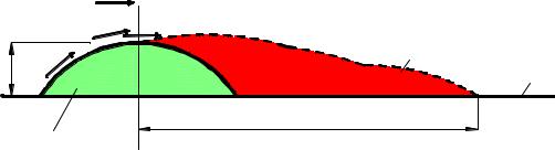
Considering the results in [5, 15], we set forth a scheme of a heat exchange surface (Fig. 2) which consists of a plate and a round semi-cylinder.
|
|
W |
0 |
|
|
|
W |
ж |
W ж |
|
|
|
||
|
|
|
1 |
|
Н |
W |
ж |
|
|
|
2 |
|||
|
|
|||
|
|
|
||
|
3 |
|
L |
|
|
|
|
||
Fig. 2. Development of movement behind a cylindrically shaped rib:
1 is an area of swirling and high turbulization; 2 is a plate; 3 is a cylindrically shaped rib; Wж is a tangential speed during flowing of the cylindrically shaped rib, m/seс;
W0 is the rate of the main liquid flow, m/seс
39