

3559
.pdfRussian Journal of Building Construction and Architecture
deformation modulus, stamps with the curvature radii from 0.2 to 0.8 m were used. The results are shown in Fig. 9.
Contact angle, degrees
Radius of the roller drum, m
Fig. 9. Dependence of the contact angle of the roller drum on the radius
Based on the dependence, the diameter of the roller rises due to an increase in the contact arc, the angle β which characterizes the residual deformation of the material changes. The dependence of the roller contact angle (β) on its radius can be given by the formula:
26.63 е–1.61 R . |
(14) |
The correlation coefficient of the equation is 0.97.
The contact angle of the roller with the material to be compacted also depends on the load transmitted to the surface. Figure 8 shows the dependence of the change in the contact angle on the linear pressure of the roller drum at its constant radius on the material.
As the linear pressure of the roller increases, so does the load on the material in the contact zone, which leads to a rise in the deformation of the material and thus in the contact angle. The dependence of the roller contact angle on the linear pressure is the following:
7.1ln q 10.1, degrees. (15) The correlation coefficient of the equation is 0.96.
Contact angle, degrees
Linear pressure, kN/m
Fig. 10. Dependence of the contact angle of the roller drum on the linear pressure of the roller drum
Based on the diagram of the interaction of the roller with a compacted material in Fig. 10, the angle β characterizes the residual deformation of the material after a roller run. A change in
60
Issue № 2 (46), 2020 |
ISSN 2542-0526 |
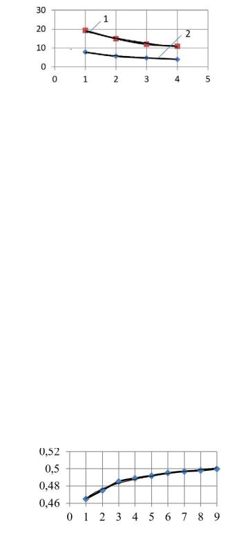
the contact angles of a drum with a diameter of 560 mm and a linear pressure of 70 N/m at different roller runs is shown in Fig. 11.
Contact angle, degrees
Number of runs
Fig. 11. Dependence of the contact angle of the roller drum with a compacted material on the number of roller runs: 1 is a contact angle β; 2 is a rear angle –– α
Based on the data, a change in the contact angles of the drum (β and α) during compaction of asphalt granulate depending on the number of roller runs is governed by a logarithmic dependence and the numerical values are given by the formulas:
6.17ln n 19.23, degrees,
2.73ln n 7.7, degrees. |
(16) |
where n is an ordinal number of a roller run. The correlation coefficient of the equation is 0.98.
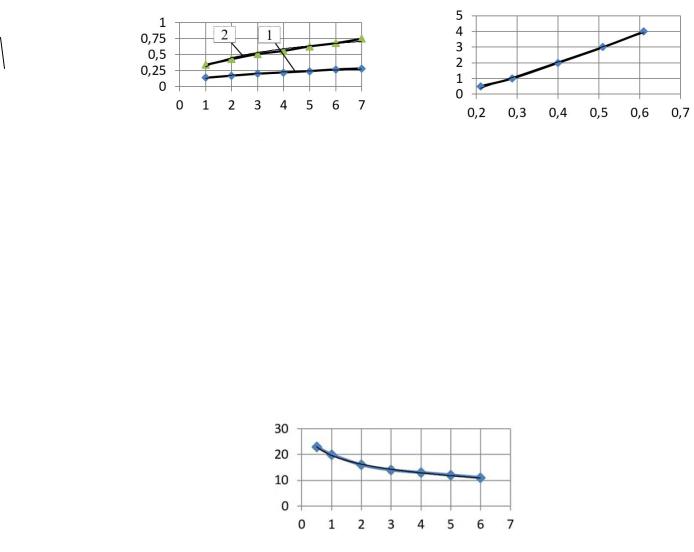
As the roller makes more runs along the track, due to an increase in the deformability of the material, it is not only the roller contact angle β that changes but the α angle also does (Fig. 12).
The analysis of the experimental data as well as processing the results of other studies allows us to conclude that there is a general pattern between the contact angles β and α, which is shown in Fig. 12.
Relative angle, α/β
Number of runs
Fig. 12. Dependence of a relative contact angle of the roller drum depending on the number of roller runs
61

Russian Journal of Building Construction and Architecture
The numerical value of the relative angle of contact of the roller with the surface of the asphalt granulate layer is given by the formula:
/ 0.016ln n 0.465. |
(17) |
The correlation coefficient of the equation is 0.99. The identified regularities of changes in the angle of contact of the drum with the layer surface make it possible to justify the contact parameters while simulating the compaction process with a roller depending on the properties of the material, parameters of the roller and structural layers.
3. Development of a mathematical model of the interaction of the roller drum with the compacted material. The diagram suggests the interaction of the roller with a compacted material that under forces applied to the roller, normal (σ) tangential (τ) stresses arise in the contact zone with the surface of a material layer. The system of equations characterizing the stress distribution along the arc of contact of the roller with the material to be compacted takes the following form:
x 0; z |
sin(z )rBd z |
1 cos(z )rBd z |
|
2 cos(z )rBd sin( z)rBd |
|||
0 |
0 |
0 |
z |
1 cos( z)rBd 2 cos( z)rBd T SX 0;
z |
z |
|
|
y 0;z |
cos(z )rBd z |
1 sin(z )rBd z |
|
2 sin(z )rBd cos( z)rBd |
|||
0 |
0 |
0 |
z |
1 sin( z)rBd 2 sin( z)rBd Q SY 0;
z z
M 0; z |
Br2 s d M |
|
|
|
|
(17) |
0 |
|
|
|
|
|
|
The initial conditions are as follows: |
|
|
|
|
|
|
at 0 QY QX FX FY SY SX 0 |
|
|
||||
at QY QX FX FY |
SY |
SX |
0 |
|
(18) |
|
The boundary conditions can be presented as follows: |
|
|
|
|
|
|
zd QY /d 0;d F X /d 0;d SX /d 0; 0X |
FY |
SY |
0. |
(19) |
||
In the system of equations the following designations are adopted: σQу are the stresses caused by the force Q; and S are the shear stresses in the material caused by the forces T and S; Sx and Sy are the projections of the force S on the x and y axes. The force S occurs due to the
62
Issue № 2 (46), 2020 |
ISSN 2542-0526 |
torque M applied to the drum axis and is a constant value along the arc of the drum contact. The numerical value is given by the expression:
|
|
S S d Br M /r . |
(20) |
0 |
|
In the final form, the solution to the system of equations characterizing the distribution of contact stresses under the roller drum takes the following form:
( А В D Ф S O ) / (A В D Ф S |
21 |
О ) 2 |
/ |
|||||||||
11 |
11 |
11 |
11 |
11 |
11 |
21 |
21 |
21 |
21 |
21 |
|
|
(A31 В31 D31 Ф31 S31 О31) 3 / ( A41 В41 D41 Ф41 S41 O41) 4 / , (21)
where Аί1, Вί1, Фί1, Dί1, Sί1, Oί1 are the coefficients of the system of equations depending on the angles of contact of the roller drum with a compacted material. The numerical value of the coefficients is given by the expressions:
А |
R 2[ y |
(С N) y ( 2М С) y |
(N М)];А |
|
R [ 2 y ( N С) y (С 3К ) y |
( 2К N)]; |
||||||
11 |
2 |
|
3 |
4 |
|
21 |
|
|
1 |
3 |
4 |
|
В11 |
R 2 [ y2(E W ) y3( 2V E) y4(W – V )];В21 R [ 2 y1( W E) y3(E 3U ) y4 ( 2U W )]; |
|||||||||||
O |
R 2 [ y ( W E) y (E 2V ) y ( V W )];O |
|
R [ 2 y (E W ) y ( 3U E) y (W 2U)]; |
|||||||||
11 |
1 |
2 |
3 |
4 |
21 |
|
1 |
1 |
3 |
4 |
|
|
D11 F 2[ y2 ( W E) y3(E 2V ) y4 ( V W )];D21 |
|
F [ 2 y1(E W ) y3( 3U E) y4 (W 2U )]; |
||||||||||
Ф F 2 [ y (С N) y ( 2 |
М С) y |
(N М)];Ф |
|
F [ 2 y ( N С) y (С 3К) y |
( 2К N)]; |
|||||||
11 |
|
2 |
3 |
4 |
|
21 |
|
1 |
3 |
4 |
|
|
S |
F 2 [ y ( N С) y (С 2М) y ( М N)];S |
21 |
F [ 2 y (С N) y |
( 3K С) y (N 2K)]; |
||||||||
11 |
1 |
2 |
3 |
4 |
|
|
1 |
1 |
3 |
4 |
||
А31 R [ y1 С 2М y2 3К С y4 М К ] ;А41 R [ y1( М N) y2(N 2К) y3 К М ];
В31 R [ y1(E 2V ) y2 ( 3U E) y4 (V – U )];В41 R [ y1( V W ) y2 (W 2U ) y3( U V )];
O31 R 1[ y1( 2V E) y2 E – 3U y4( U V) ;O41 R 1 y1(W V) y2 2U W y3(V U)];
D31 F [ y1( V E) y2 E 3U y4 U V ;D41 F y1(W V ) y2 U W y3 V U ];
Ф31 F [ y1(C М) y2( 3К С) y4(М К)];Ф41 F [ y1( М N) y2( N – К) y3( К М)]; S31 F 1[ y1( 2М С) y2(С 3К) y4( К М) ;S41 F 1 y1(N М) y2( К N) y3(М К)],
where R and F are the forces acting on the driving roller and are given by the expressions:
R R1 R2;F F1 F2 (F1 T;F2 S cos(z );R1 Q;R2 S sin(z )); K, U, M, V, N, W, C, E are thecoefficientsdependingonthepropertiesof amaterialandaregivenbythe formulas:
Кcos( – z) sin( – z) sin z;U sin( – z) cos( z) cosz;
М2 cos( – z) 2U;
V2 sin( – z)–2К; N 3 cos( – z) 3V;W 3sin( z)–3М;
С4 cos – z 4W; E 4 sin z –4 N;
63

Russian Journal of Building Construction and Architecture
where |
|
is the determiner of a system of equations which is given by the expression: |
|
|
|
|||||||||||||||||||||||||||
[y |
2 |
(l l l l ) y (l l |
l l ) y |
4 |
(l l l l )]– 2 |
[y (l l |
|
l l ) y (l l |
l l ) y |
4 |
(l l l l )] |
|||||||||||||||||||||
|
3 8 |
4 7 |
|
3 |
1 6 |
2 8 |
|
|
2 7 |
3 6 |
1 |
2 8 |
4 6 |
3 |
4 5 |
1 8 |
|
|
1 6 |
2 5 |
|
|
||||||||||
3 y l l |
l |
l |
6 |
y |
|
l l |
l l |
y |
|
|
l l l l |
4 |
y l |
l |
7 |
l l |
6 |
y |
l l |
l l |
|
y |
l l l l |
|
, |
|||||||
1 |
2 8 |
4 |
|
|
2 4 5 |
1 8 |
|
4 1 6 |
2 5 |
|
1 |
2 |
|
3 |
|
2 |
3 5 |
1 7 |
|
|
3 1 6 |
2 5 |
|
|||||||||
где l1 К U – 1U ; l2 М V 1V ;l3 N W – 1W ;l4 C E 1E ; l5 U – К 1К ;l6 V – М 1М ;l7 W – N 1N ;l8 E – C 1C ,
where μ and μ1 are the coefficients of the resistance to movement and cohesion of the drum. The analysis of the equation shows that if there is no torque (μ1 = 0), the stresses in the contact zone of the drum are distributed as follows:
|
к |
(A B D Ф ) / (A B D Ф ) 2 |
/ |
|
||||||||
|
11 |
11 |
11 |
11 |
21 |
21 |
21 |
21 |
|
|
|
|
|
|
(A |
B |
D |
Ф |
) 3 / (A |
B |
D |
Ф ) 4 |
/ . |
(22) |
|
|
|
31 |
31 |
31 |
31 |
41 |
41 |
41 |
41 |
|
|
|
Under this condition, the equation for the distribution of contact stresses along the contact arc of the driving roller corresponds to the equation for the driven roller. During compaction of a material with a small angle of internal friction, when we can conditionally assume μ = 0, the equation takes the following form:
к A11 D11 / A21 D21 2 / A31 D31 3 / A41 D41 4 / ). (23)
If there is no tractive effort, i.e., at F = 0 and μ1 = μ = 0, the stresses under the drum are given by the expression:
к А1 / А21 ²/ А31 ³/ А41 ³/ . |
(24) |
The components of the total stress in the contact zone of the driving roller of the drum are as follows:
Qу (A11 A21 2 A31 3 A41 4)/ ; Fy (D11 D21 2 D31 3 D41 4)/ ,
Qх (B11 B21 2 B31 3 B41 4) / ; Fх (Ф11 Ф21 2 Ф31 3 Ф41 4)/ ,
|
sy |
S S |
2 |
S |
3 |
S |
4)/ ; |
sx |
(O O 2 |
O 3 |
O 4)/ . (25) |
|
|
11 |
21 |
|
31 |
|
41 |
11 |
21 |
31 |
41 |
||
The resulting solution of the system of equations corresponds to the particular cases of contact of the driving roller of the drum with a compacted material in all modes of its operation. The above dependence makes it possible to identify the stresses in the contact zone of the roller of the drum with a compacted material depending on the power parameters of the roller and the properties of a compacted material.
64
Issue № 2 (46), 2020 |
ISSN 2542-0526 |
4. Results of calculations of stresses in contact zone of the roller with a compacted material. In order to identify the stresses in the contact zone of the roller with a compacted material, a software program was developed [13] which makes it possible to establish the dependence of the stresses on the number of roller runs along one track and the properties of a compacted material. The results of calculating the stress under the roller drum (for a light roller with a weight of 1.5t and a heavy roller with a weight of 12.5t) and their effect on the deformation modulus of a compacted layer of asphalt granulate are in Fig. 13.
MPа
Stress,
Number of runs
а)
Deformation modulus, MPa
Stress, MPa
b)
Fig. 13. Dependence of the stresses on the number of roller (a) deformation modulus on the stress (b): 1 is a roller with a weight of 1.5t; 2 is a roller with a weight of 12.5t
Based on the data in Fig. 13, the value of the maximum stresses under the roller of the drum increases as does in the number of runs along one track, which is associated with a decrease in the contact angle of the roller. An increase in stress leads to that in the deformation modulus of a compacted material, which contributes to a decrease in the angle of contact of the roller with the surfacing (Fig. 14).
Contact angle, degrees
Deformation modulus, MPa
Fig. 14. Dependence of the contact angle of the roller drum on the deformation modulus of a compacted material
5. Results of the experimental studies of the influence of the parameters of the rollers on the quality of compaction of an asphalt granulate layer. In order to clarify the results obtained while modeling the process of compaction of an asphalt granulate layer and the influ-
65
Russian Journal of Building Construction and Architecture
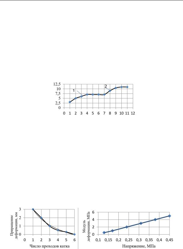
ence of the parameters of the rollers on the quality of compaction in production conditions, experimental studies were performed. A link consisting of a 1.5t roller (DM-02-VD) and a vibrating smooth drum roller (Bomag BV213D4) with a weight of 12.3t in static operation was used as compaction machines. The thickness of a layer was 0.2m, the size of the fraction was 5—20 mm. In the process of compaction, the deformation of the material layer following each run of the roller, the angle of contact of the drum with the material, density and compaction coefficient were measured using the PAB-1 device. Figure 15 shows the results of measurements of deformation following each run of the roller.
Deformation, mm
Number of roller runs
Fig. 15. Dependence of the deformation of an asphalt granulate layer on the number of roller runs: 1 is a roller DM-02-VD; 2 is Bomag BV213D4
According to the results, as the number of the roller runs along one track increases, so does the total deformation of the material layer to a certain value regardless of the parameters of the roller and then stabilizes. Thus depending on the power parameters (q, R), each roller has a specific field of application. At the same time, the residual deformation following each pass of the roller decreases accompanied by an increase in the material deformation modulus due to that in the stress in the contact zone of the roller with a compacted surface (Fig. 16).
|
|
|
|
Deformation modulus, MPa |
|
|
Deformation growth, mm |
|
|
|
|||
|
|
|
|
|
|
|
|
|
|
|
|
|
|
|
|
|
|
|
|
|
|
|
Number of roller runs |
|
|
|
Stress, MPa |
|
|
а) |
|
|
|
b) |
Fig. 16. Dependences of a deformation growth of a material following a roller run (a) and deformation modulus on the stress for a light roller (b)
66
Issue № 2 (46), 2020 |
ISSN 2542-0526 |
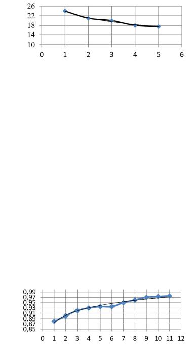
Based on the data in Fig. 16, the compaction capacity of the roller depends on the force parameters (q/r) and the properties of the compacted material characterized by the deformation modulus. With constant power parameters of the roller and its run along one track, due to an increase in the material deformation modulus, the contact angle of the drum with the layer surface changes, which leads to a rise in contact stresses under the roller of the drum. E.g., Fig. 17 shows the dependence of the drum contact angle on the number of roller runs.
Angle z, degrees
Roller runs
Fig. 17. Dependence of the contact angle of the drum on the number of roller runs
The analysis of the simulation results (Fig. 11) and the data of the experimental studies of changes in the angle of contact of the drum with a layer surface during roller runs showed that they are governed by the general laws. The maximum deformation of the compacted material is provided after 3––4 runs along one track. With subsequent runs of the roller, the increment of the layer deformation slows down due to an increase in the density of the material and at the final stage of compaction the deformation does not occur. The use of rollers at the initial stage of layer compaction whose strength characteristics exceed the ultimate strength of the material leads to the development of plastic deformations in a compacted material layer.
Change in the material density during compaction is characterized by the compaction coefficient whosevalueforanasphaltgranulate with afractionof5––20mmcanbegivenbytheformula:
Ку 0.775е0.0083 , (26)
where λ is the deformation, mm. The coefficient of the equation is 0.96.
Compaction coefficient
Number of runs
Fig. 18. Dependence of the compaction coefficient of an asphalt granulate layer on the number of roller runs
67

Russian Journal of Building Construction and Architecture
Considering the deformation of the material layer caused by stress (Fig. 15), Fig. 18 shows change in the compaction coefficient from the number of roller runs along one track.
Conclusions.
1.Ensuring the required quality of compaction of asphalt granulate depends on the compliance of the strength characteristics of a layer material with the load acting on it. Change in the thickness during the laying of a layer of asphalt granulate was found to affect the deformation and strength characteristics, which must be taken into consideration when assigning the parameters of compacting machines. An analytical dependence of the effect of the layer thickness on the ultimate strength and the deformation modulus of an asphalt granulate layer on the load has been obtained.
2.According to the results of the experimental studies, the regularities of the influence of the properties of the compacted material and the parameters of the roller on the arc of the roller contact during compaction are justified. The resulting analytical dependence for identifying the stresses in the contact zone of the drum with the material considering its deformability and the power parameters of the roller makes it possible to justify the parameters of the compaction machine depending on the properties of a material.
3.The relationships between the load and deformation of a material layer, the deformation and the coefficient of compaction under a compaction load considering the fractional composition of asphalt granulate have been experimentally established.
4.The suggested methodology for developing the technology of layers with the use of asphalt granulate enables one to ensure the required quality of compaction considering the properties of the material, the thickness of the layer to be laid and the parameters of compacting machines and can thus be employed in the development of technology for construction of road structure layers.
References
1.Aleksikov S. V., Ermilov A. A. Sravnitel'naya otsenka odnorodnosti uplotneniya asfal'tobetonnykh pokrytii gorodskikh dorog pri razlichnykh rezhimakh raboty katkov [Comparative assessment of the uniformity of compaction of asphalt concrete surfaces of urban roads in different modes of operation of skating rinks]. Nauch. vestn. VGASU. Ser. Str-vo i arkhitektura, 2014, vol. 1 (33), pp. 45––53.
2.Vasil'ev A. P. e.a. Spravochnaya entsiklopediya dorozhnika. T. I: Stroitel'stvo i rekonstruktsiya avtomobil'nykh dorog [Reference encyclopedia of road builders. Vol. I: Construction and reconstruction of highways]. Moscow, Informavtodor Publ., 2004. 505 p.
68
Issue № 2 (46), 2020 |
ISSN 2542-0526 |
3.Vasil'ev A. P. e.a. Spravochnaya entsiklopediya dorozhnika. T.II: Remont i soderzhanie avtomobil'nykh dorog
[Reference encyclopedia of road builders. Vol. II: Repair and maintenance of highways]. Moscow, Informavtodor Publ., 2004. 507 p.
4.Zubkov A. F. Metodika razrabotki tekhnologicheskikh protsessov stroitel'stva dorozhnykh pokrytii iz goryachikh asfal'tobetonnykh smesei [Method of development of technological processes for construction of road surfaces from hot asphalt concrete mixes]. Vestnik Tambovskogo gosudarstvennogo tekhnicheskogo universiteta, 2007, vol. 13, no. 1, rubrika 04, preprint no. 18, 51 p.
5.Zubkov A. F., Odnol'ko V. G. Tekhnologiya stroitel'stva asfal'tobetonnykh pokrytii avtomobil'nykh dorog
[Technology of construction of asphalt concrete road surfaces]. Moscow, Mashinostroenie Publ., 2009. 223 p.
6.Zubkov A. F., Andrianov K. A., Antonov A. I., Odnol'ko V. G. Tekhnologiya stroitel'stva i remonta dorozhnykh pokrytii nezhestkogo tipa s uchetom temperaturnykh rezhimov asfal'tobetonnykh smesei [Technology of construction and repair of road surfaces of non-rigid type taking into account the temperature conditions of asphalt concrete mixtures]. Tambov, FGBOU VO «TGTU» Publ., 2017. 300 p.
7.Igoshkin D. G., Koshkarov V. E., Nevolin D. G., Vtyurin A. V. Ustroistvo asfal'tobetonnykh pokrytii avtomobil'nykh dorog s ispol'zovaniem asfal'togranulyata [Construction of asphalt concrete road surfaces using asphalt granulate]. Innovatsionnyi transport, 2014, no. 1 (11), pp. 35––41.
8.Kalgin Yu. I., Barabas' N. A. Organomineral'nye smesi s asfal'togranulyatom dlya kapital'nogo remonta dorozhnykh odezhd [Organomineral mixtures with asphalt granulate for major repairs of road surfaces]. Vysokie tekhnologii v stroitel'nom komplekse, 2019, no. 1, pp. 42––48.
9.Nosov S.V. Razrabotka tekhnologii uplotneniya dorozhnykh asfal'tobetonnykh smesei i gruntov na osnove razvitiya ikh reologii. Diss. d-ra tekhn. nauk [Development of technologies for compaction of road asphalt concrete mixes and soils based on the development of their rheology. Doct. Diss.]. Voronezh, 2013. 366 p.
10.Panevin M. N., Kalgin Yu. I. Organomineral'nye smesi na osnove asfal'togranulyata dlya ustroistva pokrytii i osnovanii avtomobil'nykh dorog [Organomineral mixtures based on asphalt granulate for the construction of road surfaces and bases]. Nauchnyi zhurnal stroitel'stva i arkhitektury VGTU, 2016, no. 4 (44), pp. 120––127.
11.Permyakov V. B., Zakharenko A. V. Obosnovanie velichiny kontaktnykh davlenii dlya uplotneniya asfal'- tobetonnykh smesei [Justification of contact pressure values for compaction of asphalt concrete mixtures]. Stroit. i dorozh. mashiny, 1989, no. 5, pp. 12––13.
12.Permyakov K. V., Buldakov S. I. Povyshenie kachestva osnovanii dorozhnykh odezhd s primeneniem asfal'togranulyata [Improving the quality of road surface bases using asphalt granulate]. Aktual'nye voprosy proektirovaniya avtomobil'nykh dorog, 2013, no. 4 (63), pp. 168––173.
13.Senibabnov S. A., Arkhelov I. S., Zubkov A. F., Andrianov K. A., Makarov A. M. Svidetel'stvo o gosudarstvennoi registratsii programmy dlya EVM №2020611722: Raschet napryazhenii v zone kontakta val'tsa s uplotnyaemym materialov [Certificate of state registration of the computer program No. 2020611722: calculation of stresses in the contact zone of the roller with the compacted material]. Data gosudarstvennoy registratsii v Reyestre programm dlya EVM 06.02.2020.
14.Kharkhuta N. Ya. [Questions of road surface compaction theory]. Tr. Soyuzdornii «Uplotnenie zemlyanogo polotna i dorozhnykh odezhd» [Proc. Soyuzdornii «Compaction of the roadbed and road clothes»]. Moscow, 1980. P. 64––71.
69