

3553
.pdfIssue № 1(33), 2017 |
ISSN 2542-0526 |
2.Mel'kumov V. N., Kuznetsov S. N., Pavlyukov S. P., Cheremisin A. V. Nestatsionarnoe pole kontsentratsiy prirodnogo gaza v skvazhine pri ego utechke iz podzemnogo gazoprovoda [Nonstationary field of concentration of natural gas in the well in a leakage of underground pipeline]. Privolzhskiy nauchnyy zhurnal, 2008, no. 4, pp. 98––103.
3.Mel'kumov V. N., Kuznetsov I. S., Guseva L. Yu., Cheremisin A. V. Otsenka akkumuliruyushchey sposobnosti ventiliruemykh ob"emov dlya snizheniya trebuemogo vozdukhoobmena v pomeshcheniyakh [Evaluation of the accumulating capacity of the vented volume to reduce the required air exchange in premises].
Vestnik Voronezh. gos. tekhn. un-ta, 2007, vol. 3, no. 1, pp. 205––207.
4.Mel'kumov V. N., Kuznetsov S. N., Pavlyukov S. P., Kuznetsov R. N. Formirovanie kon-vektivnykh vozdushnykh potokov pri deystvii v pomeshchenii istochnika tepla [Formation of convective air flow under the action of indoor heat source]. Vestnik Volgograd. gos. arkh.-stroit. un-ta. Stroitel'stvo i arkhitektura, 2008, no. 12, pp. 76––80.
5.El'terman V. M. Ventilyatsiya khimicheskikh proizvodstv [Ventilation of chemical plants]. Moscow, Khimiya Publ., 1980. 284 p.
6.Mel'kumov V. N., Kuznetsov S. N. Dinamika formirovaniya vozdushnykh potokov i poley temperatur v pomeshchenii [Dynamics of formation of air streams and temperatures fields in premise]. Nauchnyy vestnik Voronezhskogo GASU. Stroitel'stvo i arkhitektura, 2008, no. 4, pp. 172––178.
7.Mel'kumov V. N., Kuznetsov S. N. Vzaimodeystvie ventilyatsionnykh vozdushnykh potokov s konvektivnymi potokami ot istochnikov teploty [The interaction of ventilation air flows with convection flows from heat sources]. Izvestiya vuzov. Stroitel'stvo, 2009, no. 1, pp. 63––70.
8.Kuznetsov S. N., Sklyarov K. A., Cheremisin A. V. Modelirovanie rasprostraneniya vrednykh veshchestv v smezhnykh pomeshcheniyakh [Modelling of distribution of harmful substances in the adjacent rooms].
Nauchnyy vestnik Voronezhskogo GASU. Stroitel'stvo i arkhitektura, 2008, no. 1, pp. 108––112.
9.Mel'kumov V. N., Kuznetsov S. N., Pavlyukov S. P., Cheremisin A. V. Prognozirovanie fil'tratsii gaza v grunte pri ego utechke iz podzemnogo gazoprovoda [Prediction of gas filtration in the soil when it leaks from an underground pipeline]. Izvestiya OrelGTU. Stroitel'stvo. Transport, 2008, no. 3/19(549), pp. 61––65.
10.Mel'kumov V. N., Kuznetsov S. N., Gulak V. V. Modelirovanie zadymlennosti pomeshcheniy slozhnoy konfiguratsii v nachal'noy stadii pozhara [Modeling of smoke content of premises of complex configuration at initial stage of fire]. Nauchnyy vestnik Voronezhskogo GASU. Stroitel'stvo i arkhitektura, 2010, no. 3(19), pp. 131––138.
11.Loboda A. V., Kuznetsov S. N. Ispol'zovanie metoda konformnykh otobrazheniy dlya opredeleniya poley skorostey vozdushnykh potokov v zadachakh ventilyatsii [Using the method of conformal mappings to determine velocity fields of air flows in ventilation tasks]. Nauchnyy vestnik Voronezhskogo GASU. Stroitel'stvo i arkhitektura, 2011, no. 1(21), pp. 15––22.
12.Pavlyukov S. P., Kuznetsova G. A., Kobelev A. N. Analiz sostava i prodolzhitel'nosti ekspluatatsii gazovogo oborudovaniya [Analysis of the composition and duration of operation of gas equipment]. Inzhenernye sistemy i sooruzheniya, 2012, no. 3(8), pp. 16––23.
13.Kuznetsov S. N., Kuznetsova G. A., Mkrtchyan A. G. Sostavlenie kart vliyayushchikh faktorov pri opredelenii optimal'noy trassy avtomobil'noy dorogi [Mapping the influencing factors when determining the optimal route of the road]. Inzhenernye sistemy i sooruzheniya, 2014, no. 4(17), pp. 202––206.
21

Russian journal of building construction and architecture
14.Kuznetsov I. S., Kuznetsova G. A., Mkrtchyan A. G. Integrirovannye karty vliyayushchikh faktorov dlya vybora optimal'noy trassy avtomobil'noy dorogi [Integrated maps of influencing factors to select the optimal route of the road]. Inzhenernye sistemy i sooruzheniya, 2014, no. 2(15), pp. 67––72.
15.Kuznetsov I. S., Kuznetsova G. A., Mkrtchyan A. G. Algoritmy poiska optimal'noy trassy prokladki avtomobil'noy dorogi [Algorithms for finding the optimal way of laying of roads]. Inzhenernye sistemy i sooruzheniya, 2014, no. 2(15), pp. 73––79.
16.Chow W. K., C. L. Chow, S. S. Li Simulating smoke filling in big halls by computational fluid dynamics. Modelling and Simulation in Engineering, 2011, Article ID 781252, 16 p.
17.Shu K., Huang Y., Zhang S. Reasonable layout and numerical simulation of compound ventilation mode in power transformer room, Building Energy Efficiency, 2010, vol. 38, no. 1, pp. 34––38.
18.Juan C. R., Beiza M., Jon G., Rivas A., Raúl A., Larraona G. S., Miguel I. de. Numerical modeling of the natural ventilation of underground transformer substations, Applied Thermal Engineering, 2013, vol. 51, no. 1–– 2, pp. 852––863.
19.Cox G., Kumar S. Modelling enclosure fires using CFD, in SFPE Handbook of Fire Protection Engineering, pp. 3-194–3-218, Natl Fire Protection Assn, Quincy, Mass, USA, 4th edition, 2008.
20.J. Ratnieks, A. Jakovičs, Gendelis S. Mathematical modelling of airflow velocity and temperature fields for experimental test houses. Proceedings of the 10th Nordic Symposium on Building Physics, 15––19 June 2014. Lund, Sweden, pp. 871––878.
21.Seredin P. V., Glotov A. V., Ternovaya V. E., etc. Spinodal decomposition of Ga (x) In1-x As (y) P1-y quaternary alloys. SEMICONDUCTORS, 2011, vol. 45, iss. 11, pp. 1433––1440.
22

Issue № 1(33), 2017 |
ISSN 2542-0526 |
UDC(519.9 + 518.5) : 532.54
M. Ya. Panov1, G. N. Martynenko2, A. I. Kolosov3
PROMPT MANAGEMENT ON THE BASIS OF THE DISTURBED STATE
OF THE URBAN GAS SUPPLY SYSTEM
Voronezh State Technical University
Russia, Voronezh, tel.: +7-900-304-62-51, e-mail: glen2009@mail.ru
1D. Sc. in Engineering, Prof. of the Dept. of Heat and Gas Supply and Oil and Gas Business 2PhD in Engineering, Assoc. Prof. of the Dept. of Heat and Gas Supply and Oil and Gas Business 3PhD in Engineering, Assoc. Prof. of the Dept. of Heat and Gas Supply and Oil and Gas Business
Statement of the problem. The problem of the regulation of gas flows in urban gas distribution systems by managing them promptly is addressed.
Results. A complete mathematical model is developed of the disturbed state of a distribution gas supply system in the field of a reverse analysis which formalizes the synthesis of the throttle characteristics of the system and includes a model of the disturbed system state and the system of normal equations. Based on the synthesized throttle characteristics the algorithm was proposed of a preliminary and accurate forecast of consumption in the system.
Conclusions. The throttle characteristics of the system obtained by means of modelling are the basis of forecasts of gas consumption of domestic, municipal and industrial consumers on the basis of the principles of energy reduction.
Keywords: gas supply, operational management, analysis of flow distribution.
Introduction
The state of a gas supply system can be determined using a vector of state parameters Z that includes the dependent Y and independent X variables.
Y contains the following:
––a vector of the expenses of the environment in the areas Q with the components Qi(i {I} is a total number of areas in the system);
––a vector of node pressures Р with the components Pj(j {J} is a total number of nodes);
–– a vector Pj (j {Jн} is a total number of energy nodes (EN) with a fixed node pressure);
© Panov М. Ya., Маrtynenko G. N., Kolosov А. I., 2017
23

Russian journal of building construction and architecture
–– a vector of a node supply (inflow) q with the components qj (j {Jq} is a total number of EN with a fixed node supply (inflow) including a zero supply, {Jн Jq} {Jz} where {Jz} is a total number of EN);
–– a vector S with the components Si (i {ID} is a total number of areas with throttle elements, Si is a coefficient of hydraulic resistance).
A variable X contains the following:
–– a vector S with components Si(i {IS}is a total number of areas including those with throttles, {JS JD} {J});
–– vectors D, L with components Di, Li (diameters and lengths of main pipes) i {I}, etc. The components of the vector X is included in what is called a single-valuedness condition [2—6, 11, 13]. In order to identify the initial vector Y a model of flow distribution is essential
U(Z) U(Y,X) 0.
1. Designing a flow distribution model based on the excited state of a gas supply system.
A flow distribution model [1, 2] is depicted using a ninary structural graph in its excited state containing the specified area and users’ subsystems. Modelling management in the system is suggested to be conducted using predictions of gas supply levels. The reverse analysis is a synthesis of throttle characteristics. It is designed using a square matrix МВС with unknown values Si, (i {ID}). In order to determine Si, (i {ID}), it is necessary to specify how a target product is consumed, in particular gas [14—21]. This makes it imperative to identify linearly independent connections that are excessive in relation to those form the structure of a model of the excited state of a system. The model of the excited state is obtained as a result of variation which uses the principle of least action for a gas supply network [2, 5, 8, 10, 12], i.e. there is always a clear-cut connection between the vectors Y and X. An extra connection is found in early regression analysis [5, 6, 7] which is determined using the method of least squares (MLS).
A gas distribution system has different complex interior connections [3]. The configuration of MLS for a gas supply system is adjusted to the energy and mass exchange with the environment using a set Jz of energy nodes. There is no question of the original information as it does not have to do with measuring devices and their errors, i.e. such independent variables as previously specified values of the expenses of fictional lines (Qjfa , j {Jн}) are values changing in time and influenced by subjective factors.
It is known that MLS is designed using minimization of the residual function F, here for a set Jн of the components of the vectors Р and Q that are connected with a dependence by means
24

Issue № 1(33), 2017 |
ISSN 2542-0526 |
of the Bernoulli’s equation. Considering that, let us present an objective function for a hydraulic system based on the method of least squares:
F |
|
|
j |
|
j |
|
|
j |
|
j |
|
|
2 |
|
|
j |
|
j |
|
(1) |
|
|
|
|
|
||||||||||||||||
|
S f |
|
Qfa |
|
S f |
|
Qf |
|
|
|
|
|
Qfa |
|
Qfa , |
|||||
|
j Jн |
|
|
|
|
|
|
|
|
|
|
|
|
j J |
|
j J |
|
|
|
|
where Qjfa ,Qjf are previouslyspecified and actual values of the gas expenses through a fictional area j; is the Lagrange multiplier; J , J is a set of sources and outflows of a gas distri-
bution system respectively. The second group of summands (1) confirms the hydraulics theory which runs that F should be identified as part of the continuity conditions of the environment. Asystemof normalpressuresisdesigned usingthe minimum conditionsof an objective function:
F |
|
|
f |
fa |
|
|
f |
f |
|
|
|
f |
fa |
|
1 |
|
|
|
2 |
Sj |
Qj |
|
|
Sj |
Qj |
|
|
Sj |
Qj |
|
|
0, j Jн . |
(2) |
||
fa |
|
||||||||||||||||
Qj |
|
|
|
|
|
|
|
|
|
|
|
|
|
|
|
|
|
The actual expenses Qjf are not independent within previous prediction as they are connected with a flow distribution model.
The exclusion results in a system of normal equations that meet the condition
f |
|
2 |
fa |
|
1 |
fa |
|
|
f |
|
|
idem, j Jн . |
|
Sj |
|
Qj |
Qj |
|
Qj |
|
(3) |
||||||
|
|
|
|
|
|
|
|
|
|
|
|
|
|
According to (2), (3), the specific number of extra independent connections per unit is less than of energy node flows, i.e. Jн – 1.
2. Synthesis of throttle characteristics of a gas distribution system. A complete mathematical model of the excited state of a gas distribution system in the range of reverse analysis that formalizes the synthesis of the throttle characteristics of the system and includes МВС [2, 4] and the system of normal equations are in the matrix form below:
|
|
|
|
|
|
|
|
|
|
|
|
R(rd) |
|
|
|
|
Qr |
|
|
|
|
|
|
|
|
|
|
|
|
|
|
|
|
|
|
|
|
|
|||||
|
|
|
|
|
|
|
|
|
|
|
|
|
|
|
|
|
|
|
|
|
|
|
|
|
|
|
|
|
|
|
|
|
|
|
|
|
|||||||
|
Cr |
|
Cr |
|
C f |
|
|
|
|
|
RDr (d) |
|
|
|
|
Qr |
|
|
|
|
|
MT |
|
|
|
|
|
|
; |
(4) |
|||||||||||||
|
|
|
|
|
|
|
|
|
|
|
|
|
|
|
|
|
|
|
|
||||||||||||||||||||||||
|
|
|
|
|
|
|
|
|
|
|
|
|
|||||||||||||||||||||||||||||||
|
|
|
|
|
|
|
|
|
|
|
|
|
|
|
|
|
|
D |
|
|
|
|
|
|
Р |
|
|
|
|||||||||||||||
|
|
|
|
|
|
|
|
|
|
|
|
|
|
|
|
|
|
|
|
|
|||||||||||||||||||||||
|
|
|
D |
|
|
|
|
|
|
|
|
Rf |
|
|
|
|
Qf |
|
|
|
|
|
|
|
|
|
|
|
|
|
|
|
|
|
|
|
|
|
|||||
|
|
|
|
|
|
|
|
|
|
|
|
|
|
|
|
|
|
|
|
|
|
|
|
|
|
|
|
|
|
|
|
|
|||||||||||
|
|
|
|
|
|
|
|
|
|
|
|
|
(d) |
|
|
|
|
|
|
|
|
|
|
|
|
|
|
|
|
|
|
|
|
|
|
|
|
|
|
|
|||
|
|
|
|
|
|
|
|
|
R(rd) |
|
|
|
|
|
|
|
|
|
|
|
|
|
|
|
|
|
|
|
|
|
|
|
|
|
|
|
|
|
|
||||
|
|
|
|
|
|
|
|
|
|
|
|
|
Qr |
|
|
|
|
|
|
|
|
|
|
|
|
|
|
|
|
|
|
|
|
||||||||||
|
|
|
|
|
|
|
|
|
|
|
|
|
|
|
|
|
|
|
|
|
|
|
|
|
|
|
|
|
|
|
|
||||||||||||
|
|
|
|
|
|
|
|
|
|
|
|
|
|
|
|
|
|
|
|
|
|
|
|
|
|
|
|
|
|
|
|
||||||||||||
|
|
|
|
|
К |
|
|
|
|
|
|
|
|
0 |
; |
|
|
|
|
|
|
|
(5) |
||||||||||||||||||||
|
|
|
|
|
|
|
Rr |
|
|
|
Qr |
|
|
|
|
|
|
|
|
|
|
|
|||||||||||||||||||||
|
|
|
|
|
|
|
|
|
|
|
|
|
|
|
|
|
|
|
|
|
|
|
|
|
|
|
|
|
|
|
|
|
|||||||||||
|
|
|
|
|
|
|
|
|
|
|
|
D(d) |
|
|
|
|
|
|
D |
|
|
|
|
|
|
|
|
|
|
|
|
|
|
|
|
|
|
|
|
|
|
||
|
|
|
|
|
|
|
|
|
|
|
|
|
|
|
|
|
|
|
|
Qr |
|
|
|
|
|
|
|
|
|
|
|
|
|
|
|
|
|
|
|
|
|
||
|
|
|
|
|
|
|
|
|
|
|
|
|
|
|
|
|
|
|
|
|
|
|
|
|
|
|
|
|
|
|
|
|
|
|
|
|
|
|
|
|
|||
|
|
|
|
|
|
|
|
|
|
|
|
|
|
|
|
|
|
|
|
|
r |
|
|
|
|
|
|
|
|
|
|
|
|
|
|
|
|
|
|
||||
|
|
|
|
|
|
|
|
|
|
|
|
|
|
|
|
|
|
|
|
|
|
|
|
|
|
|
|
|
|
|
|
|
|
|
|
||||||||
|
|
|
|
|
Ar |
Ar |
|
|
Af |
|
|
|
|
QD |
|
|
|
|
|
q |
|
|
|
; |
|
|
|
|
|
|
|
(6) |
|||||||||||
|
|
|
|
|
|
|
|
|
|
|
|
|
|
|
|
|
|
|
|
|
|
|
|||||||||||||||||||||
|
|
|
|
|
|
|
|
|
D |
|
|
|
|
|
|
|
Qf |
|
|
|
|
|
|
|
|
|
|
|
|
|
|
|
|
|
|
|
|
|
|||||
|
|
|
|
|
|
|
|
|
|
|
|
|
|
|
|
|
|
|
|
|
|
|
|
|
|
|
|
|
|
|
|
|
|
|
|
|
|
|
|||||
|
|
|
|
|
|
|
|
|
|
|
|
|
|
|
|
|
|
|
|
|
|
|
|
|
|
|
|
|
|
|
|
|
|
|
|
|
|
|
|
|
|
|
|
25

Russian journal of building construction and architecture
|
|
|
|
|
|
|
|
|
|
|
|
|
|
|
|
|
|
|
|
|
|
Ef |
|
(fd) |
|
Qf |
|
Ef |
|
(fd) |
, |
|
(7) |
where Rrj Srj Qrj 1 ; Rjf Sjf Qjf 1 ; jf |
Sjf |
2 QjfaQjf |
1 ; |
fj Sjf 2 |
Qjfa 2 1 ; |
||||||||||||||||||||||||||||
|
C |
|
|
|
, |
|
|
|
K |
|
|
|
, |
|
|
|
A |
|
|
|
are topological matrices of adhesive, contour and node elements per unit re- |
||||||||||||
|
|
|
|
|
|
|
|
|
|
|
|||||||||||||||||||||||
|
|
|
|
|
|
|
|
|
|
|
|
|
|
|
|
|
|
|
|
|
|
|
|
|
|
|
|
|
|
|
|
|
|
spectively; |
|
is the indicator of the degree in the Darcy Weisbach formula; Р, |
q are fixed |
||||||||||||||||||||||||||||||
node pressures and a selection (including the zero one); Т is a transportation property; the uppercase indices r and f correspond with actual and fictional network structures; the lower case index (d) belongs to the elements of a diagonal matrix.
From МВС we have a block with the lowercase index D with the size of a square matrix
(4)—(6) I I ID .
A unit matrix 
 E f
E f 
 contains two unit elements with the opposite signs in each line, the number of columns is the same as that of fictional areas, the number of lines per unit is smaller due to the condition (3), i.e. its size is Jн 1 Jн .
The size of the combined square matrix (4) and (7) is I ID I Jн 1 .
and is specific, the number of areas with throttles precisely corresponds with the number without a unit of energy node outflows (Fig. 1).
For linearization of a nonlinear model (4)—(7) the Newton’s method can be employed. A corresponding linear model of a flow distribution is below:
|
|
|
|
|
|
|
|
|
Рr |
|
|
|
|
|
|
|
|
|
|
Рr |
|
|
|
|
|
|
|
|
|
|
|
|
|
|
|
|
|
|
|
|
|
|
|
|
|
|
|
|
|
Qr |
|
|
|
|
|
|
|
|
0 |
|
|
|
|
|
|
|
|||||||||
|
|
|
|
|
|
|
|
|
(d) |
|
|
|
|
|
|
|
|
|
|
(d) |
|
|
|
|
|
|
|
|
|
|
|
|
|
|
|
|
|
|
|
|
|
|
|
|
|
|
|
|
|
|
|
|
|
|
|
|
|
|
|
|
|
|
|
|
|
|
|
|
|
|
|
|
|
||
|
|
|
|
|
|
|
|
|
РDr (d) |
|
|
|
|
|
|
|
|
|
|
РDr (d) |
|
|
|
|
|
|
|
|
|
|
|
|
|
|
|
|
|
|
Cr |
|
CDr |
|
Cf |
|
|
|
|
|
|
Qr |
|
|
|
|
|
|
|
|
|
Sr |
|
|
|
|
|
|
|
|
|
|
|||||
|
|
|
|
|
|
|
|
|
|
|
|
|
|
|
|
|
|
|
|
|
|
|
|
|
|||||||||||||
|
|
|
|
|
|
|
|
|
|
|
|
D |
|
|
|
|
|
|
|
|
|
|
D |
|
|
|
|
|
|
0 |
; |
(8) |
|||||
|
|
|
|
|
f |
|
|
|
|
|
|
|
f |
|
|
|
|
|
|
|
|||||||||||||||||
|
|
|
|
|
|
|
|
|
|
|
|
|
|
|
|
|
|
||||||||||||||||||||
|
|
|
|
|
|
|
|
|
Р(d) |
|
|
|
Qf |
|
|
|
|
|
Р(d) |
|
|
|
0 |
|
|
|
|
|
|
|
|
|
|
||||
|
|
|
|
|
|
|
|
|
|
|
|
|
|
|
|
|
|
|
|
|
|
|
|
|
|
|
|
|
|
|
|
|
|
|
|
|
|
|
|
|
|
|
|
|
|
|
|
|
|
|
|
|
|
|
|
|
|
|
|
|
|
|
|
|
|
|
|
|
|
|
|
|
|
|
|
|
|
|
|
|
|
|
|
|
|
|
|
|
|
|
|
|
|
|
|
|
|
|
|
|
|
|
|
|
|
|
|
|
|||||
Dr
K (d)
DDr (d)

 Ar ADr
|
|
r |
|
|
|
|
r |
|
|
|
|
|
|
|
|
|
|
|
|
|
|
|
|
|
|
|
|
|
|
|
|
|
|
|
|
|
|
|
|
|
|
|
|
Q |
|
|
|
|
|
D(d) |
|
|
0 |
|
|
|
|
|
|
0 |
|
; |
|||
|
|
|
|
|
|
|
|
|
|
|
|||||||||||
|
|
|
|
|
|
|
|
|
|
|
|
|
|
|
|
|
|
||||
|
|
|
|
r |
|
|
|
|
|
|
|||||||||||
|
|
|
|
|
|
|
|
||||||||||||||
Qr |
|
|
|
|
DD(d) |
|
|
|
Sr |
|
|
|
|
|
|
|
|
|
|||
|
D |
|
|
|
|
|
|
|
|
|
D |
|
|
|
|
|
|
|
|
||
|
|
|
|
|
|
|
|
|
|
|
|
|
|
|
|
|
|
|
|
|
|
|
|
|
|
Qr |
|
|
|
|
|
|
|
|
|
|
|
|
|
|
|
|
|
|
Qr |
|
|
|
|
|
|
||
|
|
|
|
(d) |
|
|
|
|
|
|
|
|
|
|
|
|
|
|
|
QDr (d) |
|
|
|
|
|
|
|
|
|
|
|
Af |
|
|
|
|
|
|
Qr |
|
|
|
|
|
|
||
|
|
|
|
|
|
||||||||||
|
|
|
|
|
|
|
|
|
|
|
|||||
|
|
|
|
|
|
|
|
D |
|
|
|
0 |
; |
||
|
|
|
Q(fd) |
|
|
|
|
|
|
|
|||||
|
|
|
|
|
|
Qf |
|
||||||||
|
|
|
|
|
|
|
|
|
|
|
|
|
|||
|
|
|
|
|
|
|
|
||||||||
|
|
|
|
|
|
|
|
|
|
|
|
|
|
|
|
|
|
|
|
|
|
|
|
|
|
|
|
|
|
|
|

 Ef
Ef 


 (fd)
(fd) 


 Qf
Qf 


 Ef
Ef 


 Ф(fd)
Ф(fd) 
 ,
,
(9)
(10)
(11)
26
Issue № 1(33), 2017 |
ISSN 2542-0526 |
where
|
|
|
|
|
|
jf |
Sjf 2 Qjfa 1 Qjf ; |
|
|
|
|
|
|||||
f |
f |
|
2 |
fa |
fa |
|
2 1 |
|
|
fa |
f |
|
|
|
|
fa |
|
|
|
|
|||||||||||||||
Фj |
Sj |
|
Qj |
Qj |
|
1 |
2 1 Qj |
Qj |
1 |
1 Qj . |
|||||||
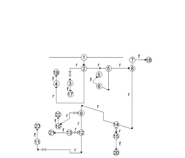
Gas Distribtion System
Fig. 1. Binary structural graph of an urban gas supply system of the medium (high) pressure stage: r, f are actual and fictional areas respectively
For the analysis of the mechanism of throttle characteristics, it is suggested that the results of a calculation experiment to model a flow distribution in the range of reverse analysis for a gas supply system of the medium pressure stage of a residential area are used (see Fig. 1) supplied with seven controlled throttles fitted on the branches of the energynode outflows. The prediction of the expense is made with eightpreviouslyspecified vlaues Qjfa with a considerable range of changes. Modelling was performed for two options for preliminary settings of the throttles with the total capacity of the system 3350 and 24985 m3/h at constant pressures in the energy nodes: Р1 = 0.5 МPа (power node) and Р16 = Р17 = Р18 = Р19 = Р20 = Р21 = Р22 = Р23 = 0.1 МPа (atmospheric pressure). The calculation experiment containing 17 specified options allowed 7 throttle characteristics to be synthesized (Fig. 2) in the relative coordinates
|
(k) |
QDi(k) |
|
|
|
(Dik) |
SDi(k) |
|
|
Q |
; |
S |
, |
||||||
Q(0) |
S(0) |
||||||||
|
Di |
|
|
|
|
|
|||
|
|
Di |
|
|
|
|
Di |
|
27
Russian journal of building construction and architecture
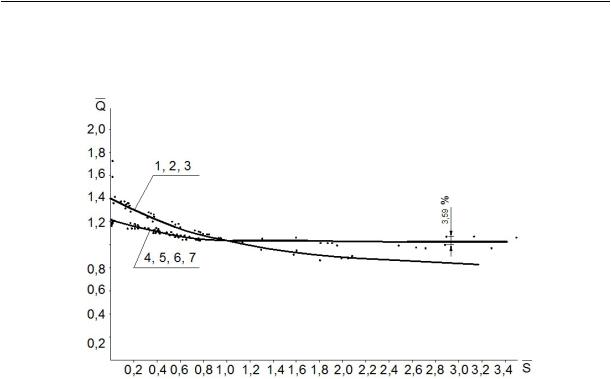
with a dispersion not over 3,5 % where QDi(0), SDi(0) are initial properties corresponding with a zero iteration [2].
Fig. 2. Throttle characteristics of a gas supply system in the relative coordinates: 1, 2, 3 for the throttles in the areas 2—4, 2—3, 5—6 respectively;
4, 5, 6, 7 for the throttles in the areas 9—10, 12—13, 12—11, 14—15 respectively
The solution of the reverse analysis is obtained for the following restrictions if
|
S(k) S0 |
, |
S(k) S0 |
, |
||
|
Di |
Di |
|
Di |
Di |
|
whereS0 |
is a resistance coefficient of a throttle as it is completely open. Note that variation |
|||||
Di |
|
|
|
|
|
|
of the throttle characteristics is not determined with error of the measuring devices but with a methodological (residual) error in the method of least squares. An important general result of the study is no variation of the throttle characteristics to the values of Qjfa specified by the user, preliminary settings of the throttles, pressure in the source, interaction of the throttles, etc.
The throttle characteristics of a system are fundamental to predicting the gas consumption by households and industries with a transition from EN-j to individual users connected to this energy nodes an be designed based on the principle of energy equivalence [2—6]. Large linearity of the objective function (3) poses a certain challenge that involves chnages in the number of iteration. The number of iterations during the experiment was within (0.5 – 50) × 103. Based on that, the algorithm of prelimiary and precise prediction can be set forth. Preliminarily it is performed using a range of changes Qjfa specified by the user and comprises modelling of flow distribution using the iteration solution of the system of equations (4)—(7), designing the throttle characteristics using the results of the calculations.
28

Issue № 1(33), 2017 |
ISSN 2542-0526 |
A precise analysis implements all of the characteristics and involves specification of the variables SDj borrowed from the above characteristics and included in the flow distribution data base (4)—(6) and the direct analysis.
Conclusions
1.There are plans to develop energy nodes using gas distribution systems to improve throttle characteristics that are the only suitable data to control a system with N remotely controlled throttles.
2.Energy-powered valves with an optical and fibre connection, shutters with the interior (operating) characteristics that recreates the configuration of throttle characteristics of a system should be employed as throttles.
References
1.Martynenko G. N., Panov M. Ya., Dmitriev I. A. Algoritm identifikatsii gidravlicheskikh kharakteristik upravlyaemykh drosseley na vetvyakh strukturnogo grafa abonentskikh podsistem [The algorithm for identifying the hydraulic characteristics of the controllable throttles in the branches of the structural graph of subscriber subsystems]. Nauchnyy vestnik Voronezhskogo GASU. Stroitel'stvo i arkhitektura, 2008, no. 3, pp. 100––105.
2.Martynenko G. N., Panov M. Ya. Analiz sushchestvuyushchey skhemy upravleniya gazopotokami v gorodskikh sistemakh gazosnabzheniya i perspektivy ee razvitiya v ramkakh operativnogo upravleniya [Analysis of the existing scheme gazobetone in urban supply systems and prospects for its development in the framework of operational management]. Nauchnyy vestnik Voronezhskogo GASU. Inzhenernye sistemy zdaniy i sooruzheniy, 2005, no. 2, pp. 23––26.
3.Martynenko G. N., Sotnikova O. A., Kolosov A. I. Issledovanie vliyaniya usloviy ekspluatatsii na prochnostnye kharakteristiki truboprovodov sistem teplogazosnabzheniya [Study of the influence of operating conditions on the strength characteristics of pipeline systems of heat and gas supply]. Nauchnyy vestnik Voronezhskogo GASU. Stroitel'stvo i arkhitektura, 2009, no. 1(1), pp. 113––117.
4.Martynenko G. N., Gnatyuk S. N. Operativnoe upravlenie gazoraspredelitel'noy sistemoy na osnove modeli vozmushchennogo sostoyaniya [Operational management of gas distribution system based on the model of the disturbed state]. Inzhenernye sistemy i sooruzheniya, 2012, no. 1(6), pp. 36––42.
5.Martynenko G. N., Luk'yanenko V. I., Isanova A. V. [Optimization of modes of gas consumption through operational management]. Trudy nauchno-tekhnicheskoy konferentsii «Fiziko-tekhnicheskie problemy energetiki, ekologii i energoresursosberezheniya» [Proc. of the scientific-technical conference "Physics and technical problems of energy, ecology and conservation"]. Voronezh, VGTU, 2013, vol. 15, pp. 128––132.
6.Martynenko G. N., Ukhlova V. V. Raschet parametrov seti dlya realizatsii protsessov operativnogo upravleniya sistemoy gazosnabzheniya nizkogo davleniya [Calculation of parameters of the network to implement processes for operationalmanagementofthe gassupplysystemlowpressure].Svidetel'stvoo gos.registratsii№11938,2008.
7.Panov M. Ya., Martynenko G. N., Aldalis Kh. Drossel'nye kharakteristiki v oblasti obratnogo analiza gorodskikh sistem gazosnabzheniya [Throttle characteristics in the field of inverse analysis of urban systems].
Nauchnyy vestnik Voronezhskogo GASU. Stroitel'stvo i arkhitektura, 2009, no. 1(13), pp. 43––50.
29

Russian journal of building construction and architecture
8.Panov M. Ya., Shcherbakov V. I., Kvasov I. S. Metodologiya faktornogo analiza vodoraspredeleniya i vodopotrebleniya [Methodology factor analysis of water allocation and water use]. Izvestiya vuzov. Stroitel'stvo, 2001, no. 5, pp. 82––87.
9.Panov M. Ya., Martynenko G. N., Luk'yanenko V. I., Bragina L. P. [Modeling of operational management of urban gas supply systems on the basis of the throttle characteristics by using an ultrasonic meter "Dnepr-7"].
Trudy nauchno-tekhnicheskoy konferentsii «Fiziko-tekhnicheskie problemy energetiki, ekologii i energoresursosberezheniya» [Proc. of the scientific-technical conference "Physics and technical problems of energy, ecology and conservation"]. Voronezh, VGTU, 2011, vol. 13, pp. 70––75.
10.Panov M. Ya., Martynenko G. N., Luk'yanenko V. I. [Operational management of the operation of urban gas supply systems]. Trudy nauchno-tekhnicheskoy konferentsii «Fiziko-tekhnicheskie problemy energetiki, ekologii i energoresursosberezheniya» [Proc. of the scientific-technical conference "Physics and technical problems of energy, ecology and conservation"]. Voronezh, VGTU, 2012, vol. 14, pp. 89––94.
11.Panov M. Ya., Martynenko G. N., Aldalis Kh. Upravlenie sistemami gazosnabzheniya s uzlovoy skhemoy otbora putevoy nagruzki [Managing supply systems with nodal selection scheme of track load]. Gazovaya promyshlennost', 2009, no. 08(635), pp. 75––77.
12.Panov M. Ya., Martynenko G. N., Aldalis Kh. Formirovanie matematicheskoy modeli operativnogo upravleniya funktsionirovaniem sistem gazosnabzheniya s ispol'zovaniem uzlovoy skhemy otbora putevoy nagruzki [Formation of mathematical models of operational performance management systems using the nodal schematic of selection track load]. Nauchnyy vestnik Voronezhskogo GASU. Stroitel'stvo i arkhitektura, 2009, no. 1(1), pp. 75––80.
13.Shcherbakov V. I., Panov M. Ya., Kvasov I. S. Analiz, optimal'nyy sintez i renovatsiya gorodskikh sistem vodosnabzheniya i gazosnabzheniya [Analysis of the optimal synthesis and the renovation of urban water supply and gas supply]. Voronezh, VGASU, 2001. 304 p.
14.Babonneau F., Nesterov Y., Vial J.-P. Design and operations of gas transmission networks. Operations Research, 2012, no. 60(1), pp. 34—47.
15.Choi H. R., Ryew S. M. Robotic system with active steering capability for internal inspection of urban gas pipelines. Mechatronics, 2002, vol. 12, no. 5, pp. 713—736.
16.Shimizu Y. [et al.]. Development of Real-Time Safety Control System for Urban Gas Supply Network. J. Geotech. Geoenviron. Eng, 2006, vol. 132, no. 2(237), pp. 237—249.
17.R´ıos-Mercado R. Z., Kim S., Boyd E. A. Efficient operation of natural gas transmission systems: A net- work-based heuristic for cyclic structures Computers & Operations Research, 2006, no. 33(8), pp. 2323—2351.
18.Sanaye S., Mahmoudimehr J. Optimal design of a natural gas transmission network layout. Chemical Engineering Research & Design, 2013, no. 91(12), pp. 2465—2476.
19.Se-gon Roh, Hyouk Ryeol Choi. Differential-drive in-pipe robot for moving inside urban gas pipelines, IEEE Transactions on Robotics, 2005, vol. 21, no. 1, pp. 1—17, DOI: 10.1109/TRO.2004.838000.
20.Tawarmalani M., Sahinidis N. V. Global optimization of mixed-integer nonlinear programs: Atheoretical and computational study. Mathematical Programming, 2004, no. 99(3), pp. 563—591.
21.Woldeyohannes A. D., Majid M. A. A. Simulation model for natural gas transmission pipe-line network system. Simulation Modeling Practices and Theory, 2011, no. 19(1), pp. 196—212.
30