

3553
.pdfIssue № 1(33), 2017 |
ISSN 2542-0526 |
It is an easy task to see from the presented analytical dependences that survivability parameterdepends of the continuity and location of the structural elements of the system defining the quantitative redistribution of loads in the structurally non-linear system, the parameters of the diagram of static-dynamic deformation of the sections of system elements and consequently, the reinforcement pattern and intensity of reinforced concrete elements.
Numerical analysis
Let us perform as an example a numerical analysis of the parameter of survivability of a twice redundant model of a reinforced concrete frame with the span l = 1.200 mm, H = 700 mm, cross section h = 120 m, b = 40 mm (Fig. 3). The girder is reinforced with symmetrical reinforcement, the diameter of 5 mm, grade А-400, area of compression and tensile reinforcement is Аs = Аs = 0.196 * 104 m2. Frame pole and girder are designed of B35 concrete. The frame is
loaded with the distributed load q 0.117 |
кН |
and concentrated parametric load imposed in |
|
м |
|||
|
|
the middle of the girder span, varying with parameter
Two variants of the system topology were analyzed. In the first variant (Fig. 3), the left pole of the frame is hinged and rigidly connected to the girder. In the second variant, this pole is hinged to the girder but it has an additional intersect at the point of connection.
Fig. 3. Structural (a) and design (b) diagrams for two variants of bounding conditions
11

Russian journal of building construction and architecture
Calculated for the specified dimensions of the section and girder reinforcement limit value of the ultimate moment in its span and support sections is 0.6 kN * m. The reduced flexural rigidity of the girder is Bred. = 0.169 Mn * m2. Since the girder section for the specified reinforcement pattern fractured brittly due to the compressive concrete deterioration as an overreinforced section, the coefficient of the excess of the failure moment over the design ultimate moment (C) is taken as 1.4 and correspondingly, the value of estimated failure moment in the span (1––1) and support (2––2) sections is Mult = 0.84 kN * m.
Having chosen the basic system in the specified variant of the mixed-mode method and having calculated coefficients of canonical equations and solved simultaneous equations (1) in
MathCAD, we find the values of the unknown M and z . Using the formula (6), we determine the minimum value of the parameter λ, at which in the sections С1…., С6 limit value of failure moment is reached. From the calculation for the 1st variant frame, the following values of λm are obtained: λ1 = 1.657, λ2 = 1.652, λ3 = 1.852, λ4 = 2.851, λ5 = 2.851, λ6 = 2.083.
For the 2nd variant frame survivability parameter values are λ1 = 2.359, λ3 = 2.795, λ4 = 3.144, λ5=3.154, λ6=1.991 respectively.
According to the specified data that in the 1st variant frame section С2 fails first and in the 2nd variant frame section С6 fails first. The 2nd variant frame is much more survivable as all values for this frame are more than λm values for the 1st variant frame. During further calculation for frames of the 1st and 2nd variants correspondingly, after cutoff of the moment tie in С2 section or С6 section and decrease of redundancy of each of the frames per unit, the λm parameter values change. Redistribution of loads in the structural system takes place and position of hazardous weak sections changes. Therefore, it can be concluded that as far as ties in the structural system fail and thus system topography changes, the coefficient of dynamic loading in the sections of structural system elements (relation Mnd 1 / Mnc ) and system destruction resistance change.
Conclusions
The proposed method of survivability parameter analysis for redundant framed structurally and physically non-linear systems of buildings and facilities provides opportunity to perform in a fairly simple way and in compliance with the physical meaning of the issue under consideration the analysis of load and dynamic loading changes in structure elements as well as the sequence of structural transformations and collapses of the sections of structural elements in case of abrupt failure of one of the bearing elements (ties).
12

Issue № 1(33), 2017 |
ISSN 2542-0526 |
The applied diagram of static-dynamic deformation of a reinforced element section makes it possible to determine dynamic loading in the loaded and dynamically loaded sections of the structural system in case of its sudden structural transformation, considering elastic-plastic properties of materials and the time of dynamic loading of the section without involvement of the body of structural dynamics.
Quantitative analysis of the reinforced redundant system (frame with different bounding conditions) found that the sequence of element sections failure, value of survivability parameter of the structural system (λ) and the coefficient of dynamic loading in the sections of structural system elements depend on the system topology and characteristics of static-dynamic deformation of the sections of its elements.
References
1.Travush V. I., Emel'yanov S. G., Kolchunov V. I. Bezopasnost' sredy zhiznedeyatel'nosti –– smysl i zadacha stroitel'noy nauki [Safety of living environment-the meaning and task of the construction of science]. PGS, 2015, no. 7, pp. 4––11.
2.Travush V. I., Kolchunov V. I., Klyueva N. V. Nekotorye napravleniya razvitiya teorii zhivuchesti konstruktivnykh sistem zdaniy i sooruzheniy [Some directions of development of the theory of survivability of structural systems of buildings and structures]. PGS, 2015, no. 3, pp. 2––35.
3.Bondarenko V. M., Kolchunov V. I. Kontseptsiya i napravleniya razvitiya teorii konstruktivnoy bezopasnosti zdaniy i sooruzheniy pri silovykh i sredovykh vozdeystviyakh [Concept and directions of development of the theory of constructive safety of buildings and structures under force and environmental impacts]. PGS, 2013, no. 2.
4.Geniev G. A., Kolchunov V. I., Klyueva N. V., Nikulin A. I., Pyatikrestovskiy K. P. Prochnost' i deformativnost' zhelezobetonnykh konstruktsiy pri zaproektnykh vozdeystviyakh [The strength and deformability of reinforced concrete structures under beyond-design impacts]. Moscow, ASV Publ., 2004. 216 p.
5.Kolchunov V. I., Androsova N. B., Kljueva N. V., Buhtijarova A. S. Zhivuchest' zdanij i sooruzhenij pri zaproektnyh vozdejstvijah [The survivability of buildings and structures under beyond-design impacts]. Moscow, ASV Publ., 2014. 208 p.
6.RF Federal Law «Tehnicheskij reglament o bezopasnosti zdanij i sooruzhenij» of 30.12.2009 № 384-FZ (Sobranie zakonodatel'stva Rossijskoj Federacii, 2009, № 1, st. 5).
7.Designers` Guide to EN 1990 Eurocode: Basis of structural design. H. Gulvanessian, J––A. Cagaro and M. Holickyr, 2002. 208 p.
8.Designers` Guide to EN 1991-1.4. Eurocode 1: Actions on structures, general actions. Part 1––4 Wind actions. N. Cook., 2007. 112 p.
9.Kljueva N. V., Androsova N. B. K postroeniju kriteriev zhivuchesti korrozionno-povrezhdaemyh zhelezobetonnyh konstruktivnyh sistem pri vnezapnyh zaproektnyh vozdejstvijah [To build a criteria of surviva-
13

Russian journal of building construction and architecture
bility of corrosion-damaged reinforced concrete structural systems under sudden beyond-design impacts]. Stroitel'naja mehanika i raschet sooruzhenij, 2009, no. 1, pp. 29––34.
10.Milejkovskij I. E., Kolchunov V. I. Neordinarnyj smeshannyj metod rascheta ramnyh sistem s jelementami sploshnogo i sostavnogo sechenij [Extraordinary mixed method of analysis of frame systems with elements of solid and composite sections]. Izvestija vuzov. Stroitel'stvo, 1995, no. 7––8, pp. 32––37.
11.Almazov V. O., Khoj Kao Zuj. Dinamika progressirujushhego razrushenija monolitnyh karkasov [The dynamics of progressing destruction of monolithic frameworks].Moscow, ASV Publ., 2013. 128 p.
12.Verjuzhskij Ju. V., Kolchunov V. I., Barabash M. S. Komp'juternye tehnologii proektirovanija zhelezobetonnyh konstrukcij [Computer technologies for design of reinforced concrete structures]. Kiev, NAU Publ., 2006. 808 p.
13.Kolchunov V. I., Kudrina D. V Jeksperimental'noteoreticheskie issledovanija prednaprjazhennyh zhelezobetonnyh jeksperimentov ram v zapredel'nyh sostojanijah [Experimentally-theoretical research of pre-
stressed concrete experiments in limit state]. Stroitel'naja mehanika i raschet sooruzhenij, 2010, no. 3, pp. 14––17.
14.Tamrazjan A. G. Resurs zhivuchesti –– osnovnoj kriterij vysotnyh zdanij [Resource survivability is the main criteria of high-rise buildings]. Zhilishhnoe stroitel'stvo, 2010, no. 1, pp. 15––18.
15.Hadia N. M. A., Ryabtsev S. V., Seredin P. V., etc. Effect of the temperatures on structural and optical properties of tin oxide (SnOx) powder. PHYSICA B-CONDENSED MATTER, 2010, vol. 405, iss. 1, pp. 313––317.
14

Issue № 1(33), 2017 |
ISSN 2542-0526 |
HEAT AND GAS SUPPLY,VENTILATION,AIR CONDITIONING,
GAS SUPPLY AND ILLUMINATION
UDC 644.1
S. N. Kuznetsov1
A SELECTION OF VENTILATION MODE IN PREMISES WITH MOVING
SOURCES OF HARMFUL SUBSTANCES
Voronezh State Technical University
Russia, Voronezh, tel.: +7 (4732) 71-53-21, e-mail: kuznetvrn@mail.ru
1 D. Sc. in Engineering, Prof. of the Dept. of Heat and Gas Supply and Oil and Gas Business
Statement of the problem. When designing the ventilation systems of industrial premises with moving sources of harmful substances, it is necessary to choose an effective scheme of ventilation. Results. Based on the turbulent exchange of non-stationary equation, a mathematical model of transport of harmful substances in the room with the moving source was developed. The model is implemented as a computer software in MatLab and Simulink package.
When driving hazardous substance sources in the longest room in one direction most effective air exchange scheme is a scheme with the air flow towards the source. When moving sources of harmful substances in different directions is the most effective air exchange scheme with a uniform supply and removal of air along the length of the room.
Conclusions. The proposed approach allows one to select a scheme and the amount of air to areas with moving sources of harmful substances more effectively utilizing the fresh air and increase the effectiveness of ventilation.
Keywords: ventilation, moving source, mathematical model.
Introduction
Designing of ventilation systems of industrial premises with moving sources of hazardous substances (car tonnels, industrial containers, etc.) involves a challenging selection of an effective scheme of air exchange due to non-stationary concentration field of hazardous substances. A study of concentration fields of hazardous substances in industrial premises in natural conditions or the air and heat model is commonly associated with a large amount of experiments. This paper sets forth a mathematical model of concentration fields for choosing an effective scheme of air exchange [3, 9, 11, 17, 18, 20].
© Kuznetsov S. N., 2017
15

Russian journal of building construction and architecture
Mathematical model
Let us consider a relatively large ventilated premises and small transverse sizes with stationary heat flows.In order to calculate a non-stationary concentration field emerging in this premises as a source of hazardous substances moves, it is necessary to solve a system of differential equations including the Navier-Stokes equation, of continuity and turbulent exchange [1, 4, 7, 14, 15, 19]. The solution of the above equations in a general threedimensional case is rather challenging.
Considering that the premises is large and has small transverse sizes, let us assume that the distribution of air velocitys and concentrations of hazardous substances along the width and height of the premises. Then calculating the dynamics of the distribution of concentrations comes down to solving a one-dimensional equation of turbulent exchange [2, 5, 6, 8, 10]:
c |
u |
c |
|
|
A |
c |
g x,t , |
(1) |
|
t |
x |
x |
x |
||||||
|
|
|
|
|
where с is the concentration of a hazardous substance, mg/m3; t is the time, sec; и is the average velocity of air flow along a transverse section of the premises, m/seс; х is the distance along the premises, m; A is the coefficient of turbulent exchange, m2/sec; g(х,t) is the function of a source of a hazardous substance.
The initial condition for solving the equation is the distribution of a hazardous substance along the premises at the initial point in time and the boundary one is a hazardous substance in the supply air. The average velocity of the air flow alogn the transverse section is distributed as a ratio of air consumption to the area of the transverse section of the premises.
The function of the source of the hazardous substance is given by the expression
G0 |
at _vt 0,5l x vt 0,5l |
|
|
|
|
|
, |
(2) |
|
|
||||
g x,t lS |
|
|||
|
|
|
|
|
0_at _ x vt 0,5lx vt 0,5l |
|
|
||
where G0 is intensity of the hazardous substance, mg/sec; l is the length of the source of the hazardous substance, m; S is the area of the transverse section of the premises, m2; v is the velocity of the source of the hazardous substance, m/sec.
The energy introduced by the supply air is given by the ratio [5, 12, 13]:
пс |
M v2 |
, |
(3) |
|
|||
n 2Mп |
|
|
|
where М is the mass of the air supplied into the premises; is a correction coefficient for the velocity pressure; v is the average speed of the output air of the fan inlet, m/sec; Мп is the air mass in the volume of the premises.
16
Issue № 1(33), 2017 |
ISSN 2542-0526 |
The energy introduced into the premises by the moving source of the hazardous substance:
|
|
|
kFv3 |
|
|
|
|
|
|
t |
|
, |
(4) |
||||
ma |
2g |
3600 |
||||||
|
|
|
|
|
where k is the coefficient of aerodynamic resistance of the moving source; Ft is the area of the transverse section of the source, m2; v is the velocity of the source, m/sec; is the average time of the motion of the source, sec.
The coefficient of turbulent exchange is given by the formula [5, 16]:
1 |
4 |
|
|
A 0,25 3l3 |
, |
(5) |
|
where l is the crucial size of the premises, m.
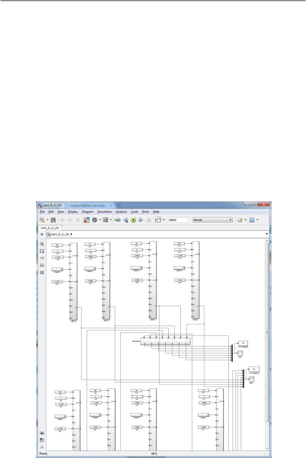
Implementation of the mathematical model
MatLab and Simulink in combination with the C ++ programming language were employed to design an environment for the mathematical model of the transfer of the hazardous substance in the premises with the moving source.
Fig. 1. Software for calculating transfer of hazardous substances in premises with a moving source in Simulink
17

Russian journal of building construction and architecture
Simulink is an environment for modelling synamic systems providing an interactive graphic environment and a user-friendly library to design and model systems changing in time. Simulink provides tools for hierarachical modelling, data management and settings. Simulink contains a large library of functions and common algorithm and structural blocks. In order to design a model, user sections to be employed for particular domains are created. After it is designed, it is dynamically modelled and evaluated. Fig. 1 presents the calculation of transfer of hazardous substances in premises with moving sources in Simulink.
The software enables the dynamics of concentrations in large premises to be computed in different schemes and air exchange, velocities and intensities of sources of hazardous substances.
Calculations using the mathematical model
The developed software was employed for choosing an effective scheme of a factor of air exchange in the premises with the length of 100 m, width of 12 m, height of 8 m.
The factor of air exchange was 5 and 2 h-1, the velocity of the inlet air is 3 m/seс. The source of a hazardous substance with the intensity of 785 mg/seс was moved along the premises with the speed of 0,2...10 m/seс. The number of finite volumes in calculating the turbulent exchange was taken to be 50. Five air exchange schemes were studied that are most common in designing long premises.
The air exchange scheme 1 involves supply of the inlet air from one side of the premises and removal of the air from the opposite one with both the air and source of a hazardous substance moving in the same direction.
The air exchange scheme 2 involves supply of 50% of the total the inlet air from the opposite ends of the premises and its removal along the centre of the premises.
The air exchange scheme 3 involves supply of the inlet air identically to scheme 2, the air is removed evenly along the premises.
The air exchange 4 involves even supply of the air along the premises and its removal identically to scheme 3.
The air exchange scheme 5 involves supply of the entire volume of the inlet air along the centre of the premises and its removal of the air identically to scheme 3.
The air exchange scheme 6 involves supply of the entire volume with one end of the premises and its removal from the opposite end with the same direction of the air motion and source of the hazardous substance.
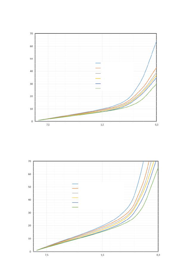
For all of the above schemes the air exchange scheme using the developed answers, the concentrations at different velocities of the source of the hazardous substances. The dependence
18
Issue № 1(33), 2017 |
ISSN 2542-0526 |
of the maximum concentration of a hazardous substance in this object on the velocity of the source of a hazardous substance is in Fig. 2 and 3.
Peak concentration of a hazardous substance, mg/m3
Scheme of air exchange 1
Scheme of air exchange 2
Scheme of air exchange 3
Scheme of air exchange 4
Scheme of air exchange 5
Scheme of air exchange 6
Velocity of the source of a hazardous substance, %
Fig. 2. Dependence of peak concentrations of a hazardous substance on the velocity of the source for different schemes o f air exchange with the factor of air exchange 5 h-1
Peak concentration of a hazardous substance, mg/m3
Scheme of air exchange 1
Scheme of air exchange 2
Scheme of air exchange 3
Scheme of air exchange 4
Scheme of air exchange 5
Scheme of air exchange 6
Velocity of the source of a hazardous substance, %
Fig. 3. Dependence of peak concentrations of a hazardous substance on the velocity of the source for different schemes of air exchange with the factor of air exchange 2h-1
19

Russian journal of building construction and architecture
The results show that when the source of a hazardous substance and airflow move in one direction, there is an area of extremely high concentrations around the source, which leads to a drastic increase in peak concentrations and conversely, when the source and airflow move in the same direction, there is even distribution of a hazardous substance along the premises with extremely low peak concentrations.
When sources of a hazardous substance move along a long premises in the same direction, the most effective scheme of air exchange is 1 when the airflow moves towards the source. When sources of a hazardous substance move in different directions, the most effective scheme of air exchange is 4.
Conclusions
Based on the non-stationary equation of turbulent exchange, a mathematical model of transfer of a hazardous substance in the premises with a moving source.
The developed model is implemented as a software in MatLab and Simulink. The sfotware is designed to calculate the dynamics of concentrations in long premises for different schemes and factors of air exchange, velocities and intensities of sources of hazardous substances.
The developed software was used to choose an effective scheme of air exchange of the premises with moving sources of a hazardous substance. The results of the calculations of six air exchange schemes, different factors of air exchange and velocities of a source.
When sources of a hazardous substance along long premises in one direction, the most effective scheme of air transfer is one when the airflow moves towards sources.
When sources of a hazardous substance move in different directions, the most effective scheme of air exchange is one with even supplyand removal of the air along the premises.
In choosing a scheme of air exchange in premises with moving sources of hazardous substances, what is to avoid is when a source and airflow move in the same direction as that leads to areas with extremelyhigh concentrations that are significantlyhigher than the average ones.
The suggested approach enables a scheme and scope of air exchange to be chosen for premises with moving sources of hazardous substances that uses the inlet air and thus the performance of the general ventilation to be improved.
References
1. Mel'kumov V. N., Kuznetsov S. N., Cheremisin A. V., Sklyarov K. A. Nestatsionarnye protsessy formirovaniya sistemami ventilyatsii vozdushnykh potokov v pomeshcheniyakh [Nonstationary processes of the formation of the ventilation air flow in rooms]. Izvestiya Orlovskogo gos. tekhn. un-ta. Stroitel'stvo i transport, 2007, no. 3––15, pp. 36––42.
20