

3273
.pdfRussian Journal of Building Construction and Architecture
weight of the subgrade and the load during traffic considering the correction factors; Сс is the arch coefficient for rack piles:
Cc 1.95 |
h |
0.18 1.95 |
0.5 |
0.18 3.07. |
|
d01 |
0.3 |
||||
|
|
|
Let us insert certain values c´ and Сс into formula (13) and get additional vertical stresses on the pile heads as a result of the arched effect that occurs in the soil between the adjacent pile heads:
Pc´ c´ |
C d |
|
2 |
196.5 |
3.07 0.30 |
|
2 |
||
|
c |
01 |
|
|
0.50 |
|
666.7 kN / m2. |
||
|
|
h |
|
|
|
|
|
|
|
Then using the formula in [17], the distributed load was calculated, which is perceived by the geocell material between the adjacent pile heads:
W |
|
|
s c´ |
|
s2 |
d |
2 |
|
Pc´ |
|
, |
(15) |
|
|
|
2 |
01 |
|
|||||||||
T1 |
|
s |
2 |
d01 |
|
|
|
´ |
|
|
|||
|
|
|
|
|
|
|
c |
|
|
||||
where s B2 d02 5.64 0.5 6.14 m is the the distance between the axes of the adjacent
piles. |
|
|
|
|
|
|
|
|
|
|
|
|
|
|
|
|
s ´ |
|
|
P´ |
|
6.14 196.5 |
|
174.74 |
|
|
|||
WT1 |
|
|
c |
|
s2 d012 |
c |
|
|
|
|
6.142 0.32 |
196.5 |
1199.60 kN / m. |
|
s |
2 |
d01 |
2 |
´ |
6.14 |
2 |
2 |
|
||||||
|
|
|
|
c |
|
|
0.3 |
|
|
|
||||
The reaction of the underlying soil under the geogrid between the heads of adjacent |
|
|||||||||||||
piles is given by the formula: |
|
|
|
|
|
|
|
|
|
|||||
|
|
|
|
|
WT 2 Pstr 2 |
s d01 123 6.14 0.3 718.3 kN / m. |
(16) |
|||||||
The distributed load, which is perceived by the geogrid between the adjacent pile heads, is calculated as:
WT WT1 WT 2 |
1199.60 718.3 481.28 kN / m. |
(17) |
Knowing the magnitude of the load that is perceived by the geocell material between the adjacent heads of the WT piles, the total tensile force in the geocell material can be identified using the formula:
T |
|
WT |
1 |
1 |
, |
(18) |
|
2d01 |
6 |
||||||
rp |
|
|
|
|
where 4% is the maximum possible ultimate stretching of the geocell material, which is given by the formula:
0.04 s d01 0.04 614 30 23.36 sm, |
(19) |
70

Issue № 2 (50), 2021 |
|
|
|
|
|
|
|
ISSN 2542-0526 |
|||
T |
|
WT |
1 |
1 |
|
481.28 |
1 |
1 |
805 kN/m2 |
8.05 kg /sm2. |
|
2d01 |
6 |
2 0.30 |
6 0.2336 |
||||||||
rp |
|
|
|
|
|
|
|||||
After obtaining the value of the total tensile force in the geocell material Trp, the maximum tensile force per unit of the reinforcing geocell material Trp can be given by the formula:
Tr Trp 8.05 0.12 0.97 kg /sm, |
(20) |
where 0.12sm is the wall thickness of the geogrid taken based on [13]. |
|
Let us check the tensile strength condition of the geocell material according to the formula: |
|
TD T , |
(21) |
r |
|
fn |
|
where Тr = 0,97 kg/cm is the maximum tensile force per unit of reinforcing geocell material; ТD = 5 kg / cm is the tensile strength of a geocell material (a spatial geogrid of the «ST» brand with a cell size of 20 × 20 cm and a height of 15 cm) taken based on [13]; fn = 1.0 is the coefficient of reliability considering the class of the structure (road) is taken based on [11].
At fn 1 5 кг /см 0,97 кг /смthe condition is met.
The efficiency of the structure is improved considerably if the geocell material is laid on top of the geotextile material, which prevents the aggregate particles from passing through the geocell material into soft ground.
Conclusions. As a result of experimental and theoretical studies, an effective construction of the subgrade has been developed, protected by a patent for a useful model No. 156221 [7], which ensures the reliability of the design and construction of highways in spots experiencing seasonal freezing of soils. Considering domestic and foreign experience in the construction of highways on soft soils [3, 5, 10, 11, 18––29], it can be concluded that strengthening the structure of the subgrade with double-cone piles reinforced with geotechnical materials is of special interest. This is due to the novelty of the approach to addressing this engineering problem in the construction of highways in severe climatic and engineering and geological conditions. The structure of the subgrade on a reinforced subsoil with double-coned piles reinforced with geotechnical materials can be considered one of the alternative viable options for constructing the subgrade by replacing soft soil.
References
1. Bartolomei A. A., Omel'chak I. M., Yushkov B. S. Prognoz osadok svainykh fundamentov [Forecast of pile foundation sediment]. Moscow, Stroiizdat Publ., 1994. 180 p.
71

Russian Journal of Building Construction and Architecture
2.Burgonutdinov A. M. Obosnovanie sposobov stroitel'stva i remonta lesovoznykh avtomombil'nykh dorog, prepyatstvuyushchikh obrazovaniyu treshchin (na primere Permskogo kraya). Diss. kand. tekhn. nauk [Justification of methods of construction and repair of logging roads that prevent the formation of cracks (on the example of the Perm Region). Cand. eng. sci. diss.]. Ioshkor-Ola, 2012. 57 p.
3.Gaev D. A., Gavrish V. V. Sovremennye geosinteticheskie materialy i oblasti ikh primeneniya v stroitel'stve [Modern geosynthetic materials and their applications in construction]. Budushchee nauki, 2013, vol. 2, pp. 131––139.
4.Dolmatov B. I. Mekhanika gruntov, osnovaniya i fundamenty (vklyuchaya spetsial'nyi kurs inzhenernoi geologii) [Soil mechanics, foundations and foundations (including a special course in engineering geology)]. Saint Petersburg, Lan' Publ., 2012. 416 p.
5.Kleveko V. I. Issledovanie raboty armirovannykh glinistykh osnovanii [Investigation of the work of reinforced clay bases]. Vestnik PNIPU Stroi-tel'stvo i arkhitektura, 2014, no. 4, pp. 101––110.
6.Yushkov B. S., Dobrynin A. O., Repetskii D. S. MPK7 E02D 5/30. Svaya [IPC7 E02D 5/30. Pile]. Patent RF, no. 2004121946/2242234, 2004.
7.Degtyar'A. A., Yushkov B. S. E02D 17/18. Konstruktsiya zemlyanogo polotna avto-mobil'noi dorogi
[E02D 17/18. Construction of the roadbed roadbed]. Patent RF, no. 156221, 2015.
8.Ponomarev A. B. Vzaimodeistvie polykh konicheskikh svai s okruzhayushchim gruntom. Avtoref. diss. kand. tekhn. nauk [Interaction of hollow conical piles with the surrounding soil. Cand. eng. diss. abstr.]. Perm', 1991. 16 p.
9.Posobie po proektirovaniyu zemlyanogo polotna avtomobil'nykh dorog na slabykh gruntakh (k SNiP 2.05.02-85) [Manual for the design of the roadbed on weak soils (to SNiP 2.05.02-85)]. Stroiizdat, 1989. 192 p.
10.Pshenichnikova E. S., Khusainov I. Zh., Zhigur Yu. L. [Investigation of the deformation of a layer consisting of a bulk lattice filled with sand]. Novosti v dorozhnom dele [News in the road business]. Moscow, Informavtodor Publ., 2006, vol. 3, pp. 16––24.
11.Pshenichnikova E. S. [Construction of a pilot site with the use of a volumetric plastic geogrid "Geoveb" in the I road-climate zone]. Sb. nauch. tr. GosDorNII «SoyuzDorNII» [Collection of scientific works of the State Research Institute "Soyuzdornii»]. Moscow, Gos. dorozh. nauch.-issled. in-t FGUP «Soyuzdornii», 2001, vol. 201, pp. 63––67.
12.Repetskii D. S. [Investigation of the interaction of small-scale two-cone piles with the surrounding clay soil]. Materialy Mezhdunar. nauch.-tekhn. konf. [Materials of the International Scientific and Technical Conference]. Perm', 2008, pp. 180––186.
13.Rekomendatsii po primeneniyu prostranstvennykh georeshotok marki «ST» [Recommendations for the use of spatial geogrids of the "ST" brand»]. Moscow, 2005. 46 p.
14.SNiP 2.02.03-85. Svainye fundamenty [SNiP 2.02.03-85. Pile foundations]. Moscow, GP TsPP Publ., 1995. 48 p.
15.Khamidullin K. A. Issledovanie raboty rombovidnykh svai v sil'noszhimaemykh puchinistykh gruntakh. Diss. kand. tekhn. nauk [Investigation of the operation of diamond-shaped piles in highly compressible heaving soils. Cand. eng. diss.]. Moscow, 1978. 173 p.
16.Yushkov B. S. Eksperimental'nye i teoreticheskie osnovy rascheta fundamentov iz dvukhkonusnykh svai, ustraivaemykh v sezonnopromerzayushchikh gruntakh [Experimental and theoretical foundations for the calculation of foundations made of two-cone piles arranged in seasonally freezing soils]. Perm', 2014. 310 p.
72
Issue № 2 (50), 2021 |
ISSN 2542-0526 |
17.BS 8006-1:2010. Code of practice for strengthened/reinforced soils and other fills. BSI, 2010. 258 p.
18.Adams S. A., Amofa N. Y. Opoku – Boahen R. Effect of Geogrid Reinforced Subgrade on Layer Thickness Design of Low Volume Bituminous Sealed Road Pavements. International Refereed Journal of Engineering and Science (IRJES) ISSN (Online) 2319-183X, (Print) 2319-1821, 2014, vol. 3, iss. 7, pp. 59––67
19.Das B. M. Use of geogrid in subgrade-ballast system of railroads subjected to cyclic loading for reducing maintenance. Sacramento, USA, California State University, 2010.
20.Harinder. D, Shankar S. Experimental Study to Reinforce The Weak Subgrade Soil for Low-Volume Roads by Coir Geotextile Mats. Journal of Geoscience, Engineering, Environment, and Technology, 2018, vol. 03, no. 01.
21.Jacobs F., Ziegler M., Vollmert L., Ehrenberg H. Explicit design of geogrids with a nonlinear interface model. Proc. of the 10th Int. Conf. on Geosynthetics. Essen, German Geotechnical Society (DGGT), 2014.
22.Kief O., Schary Y., Pokharel S. K. High-modulus geocells for sustainable highway infrastructure. Indian Geotechnical Journal, 2015, vol. 45, iss. 4, pp. 389––400.
23.Meyer N. Determination of the bearing capacity of geocell reinforced soil over soft subgrade with static and dynamic plate load tests. Institute of Geotechnical Engineering and Mine Surveying, TU Clausthal, 2007.
24.Mittal A., Shukla S. Effect of Geosynthetic Reinforcement on Strength Behaviour of Weak Subgrade Soil. Materials Science Forum, 2019, pp. 225––230.
25.Parsons R., Jowkar M., Han J. Performance of geogrid reinforced ballast under dynamic loading. Nebraska, USA, University of Nebraska-Lincoln, 2012.
26.Wang Z., Jacobs F., Ziegler M. Experimental and DEM investigation of pull-out behaviour of geogrid embedded in granular soil. Proc. of the 10th Int. Conf. on Geosynthetics. Essen, German Geotechnical Society (DGGT), 2014.
27.Yee T. W., Lim L. K., Ter Harmsel M., Choi J.C., Hwang S. P. Geotextile tubes as rockfill replacement for construction of polder dike at Saemangeum, Korea. Proc. of the 10th Int. Conf. on Geosynthetics. Essen, German Geotechnical Society (DGGT), 2014.
28.Ziegler M., Jacobs F. Laboratory testing of the compound behavior of geogrid reinforced soil. Proc. of the 10th Int. Conf. on Geosynthetics. Essen, German Geotechnical Society (DGGT), 2014.
29.Ziegler. М. Application of geogrid reinforced constructions: history, recent and future developments. Modern Building Materials, Structures and Techniques, MBMST, 2016, pp. 42––51.
73

Russian Journal of Building Construction and Architecture
DOI 10.36622/VSTU.2021.50.2.006
UDC 624.21.09
V. A. Shendrik1
STRUCTURAL EVALUATION OF REINFORCED CONCRETE COLUMN WITH COMPOSITE GFRP SHELL –– A STRUCTURAL ELEMENT OF BRIDGE PIER
Saint Petersburg State University of Architecture and Civil Engineering1
Russia, Saint Petersburg
1PhD student of the Dept. of Roads, Bridges and Tunnels, e-mail: vicinshendrik@yandex.ru
Statement of the problem. It’s considered the problem of developing a methodology for structural evaluation of hybrid design - a reinforced concrete column combined with external composite GFRP (glass-fiber-reinforced-plastic) shell. This hybrid design is intended for bridge piers.
Results. As a result of a study, theoretical relationships were formulated to determine the longitudinal and transverse stresses and relative deformations of hybrid column structural elements. The developed formulas take into account the cooperation of triaxial compressed concrete core and an anisotropic composite GFRP shell.
Conclusions. The obtained theoretical dependences of the hybrid column’s elements behavior make it possible to develop a structural evaluation methodology of bridge piers hybrid columns. The findings of the investigation are proposed to be applied in the structural evaluations of the bridges piers hybrid columns with composite GFRP elements.
Keywords: bridges, support pillars of bridges, composite materials, glass-fiber-reinforced-plastic-tubes, hybrid structures.
Introduction. Over the past few decades recent, there has been a considerable rise in the load on the structures of bridge structures, thus there is a need for their load-bearing capacity to be icnreased. Besides, the structures of bridge piers, made mainly of reinforced concrete, are being negatively impacted by the environment. Therefore, intensive corrosion occurs leading to a significant reduction in their durability and reliability [13]. Currently, there is an inadequate service life of bridge structures due to rising loads and traffic intensity [5, 15]. These make it necessary to increase the load-bearing capacity and durability of bridge structures. Composite materials are presently known to have greater durability compared to the commonly used concrete and steel [9, 14], which can considerably increase the service life of building structures.
© Shendrik V. A., 2021
74
Issue № 2 (50), 2021 |
ISSN 2542-0526 |
In particular, those composites which consist of glass fibers impregnated with polymeric binders are not inferior to reinforced concrete in strength and rigidity, and in terms of resistance to aggressive environmental factors, such fiberglass can outperform reinforced concrete and metals. The use of hybrid structures in bridge construction combining the advantages of the commonly used in reinforced concrete supports and innovative fiberglass would potentially increase both the load-bearing capacity (due to the high strength of KM) and durability of bridge structures due to resistance to negative environmental impact. The introduction of hybrid structures in the supports of bridge structures caters for the current needs of the bridge industry. As this involves the use of new materials, the ongoing study discusses the operation of hybrid struts only in bridge piers on small and medium-sized overpasses, overpasses and overground pedestrian crossings, except the supports of structures across water barriers or highlands.
The nuances of this research area are characterized by publications of domestic and overseas scientists. Data on the properties of composites has been presented by V. V. Vasiliev and Yu. M. Tarnopolsky [9], A. A. Berlin and M. L. Kerber [14]. Criteria for the strength of concrete have been developed in the studies by O. Ya. Berg [2, 3], Yu. N. Malashkin [12], N. I. Karpenko [7, 8], A. V. Yashin [16]. The strength of reinforced concrete struts has been investigated by A.A. Gvozdev [4], L. K. Luksha [11]. A. N. Yashnov, B. V. Pyrinov, А. N. Ivanov [6] developed the span structures of bridges with fiberglass beams. Overseas scientists D. Kendall [20], C. Hamrick [18] are actively engaged in the introduction of composite materials in the span structures of bridges. T. A. Hoffard and L. J. Malvar [19], H. M. Dawood and M. ElGawady [17], P. B. Potyrala [21], R. J. Watson [22] have examined the operation of reinforced concrete columns reinforced with rigid shells.
Presently composite materials in bridge construction are largely used in the construction of span structures. A considerable roadblock for using fiberglass in the construction of supports of bridge structures is the lack of methods for their calculation. Hence composites are still commonly used in the supports of bridge structures only for strengthening load-bearing structures. Currently there is a need to investigate the specifics of the work of hybrid fiberglass-reinforced concrete structural elements of the supports of bridge structures and to design a method for calculating their load-bearing capacity. The objective of the study is to formulate theoretical dependences for estimating the load-bearing capacity of a hybrid stand with a composite shell.
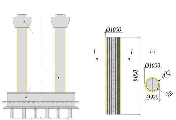
1. Design of a hybrid rack for supports of bridge constructions. In order to address the objective of the study, the design of a reinforced concrete support for bridge structures was developed and improved as shown in Fig. 1 a.
75
Russian Journal of Building Construction and Architecture
а) |
b) |
Pump
Cut
Hybrid
rack
Grillage
Fig. 1. Suggested design of a rack support of bridge constructions: a) the general look; b) hybrid reinforced concrete rack whose construction includes an outer fiberglass shell
What makes this structure different from the applied analogs of reinforced concrete rack supports are hybrid racks whose external concrete surface is enclosed in a fiberglass cover (similarly to a fixed timbering). Reinforced concrete structures are known where the load-bearing capacity of the concrete core increases considerably [4, 10, 11]. But the methods of their calculation are made for racks with steel shells and cannot be employed for calculating racks with fiberglass shell having anisotropic properties. Additionally, steel shells tend to have a low resistance to corrosion. Therefore from the perspective of durability it is most viable to use the fiberglass covers capable to resist long-term aggressive influences of external environment in racks of supports of bridge constructions. A hybrid reinforced concrete rack with an outer diameter of D = 1000 mm and a height of L = 8 meters was considered. The hybrid rack as an additional load-bearing structural element has an outer fiberglass shell (Fig. 1 b) with an inner diameter d = 920 mm and a wall thickness δ = 40 mm.
2. Theoretical dependences for identifying the lateral pressure of the concrete core on the shell of the hybrid rack. When the hybrid rack is compressed, extra transverse stresses
76
Issue № 2 (50), 2021 |
ISSN 2542-0526 |
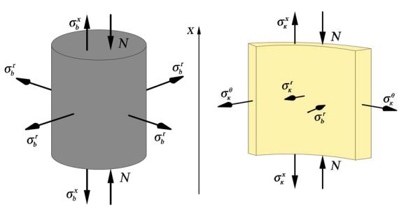
of interaction of the concrete core with the anisotropic composite shell occur. Hence in order to calculate the load-bearing capacity of the hybrid rack, it is necessary to consider the additional strengthening of the strength of the enclosed concrete core, which is in a three-axis stress-strain . As the shell is close to the concrete of the hybrid rack, when the rack is compressed, its outer shell prevents the free transverse expansion of the concrete core. This being the case, the concrete rod of the hybrid rack transmits the internal stresses arising in it not only to the base, but also to the outer fiberglass shell (Fig. 2). Therefore the concrete core works in conditions of non-uniaxial, but triaxial (volumetric) compression, which causes a significant increase in the load-bearing capacity of the hybrid rack.
а) |
б) |
Fig. 2. Three-dimensional stress-strain of the elements of the hybrid rack: a) concrete core, b) fiberglass shell
Fig. 2 denotes N as the external longitudinal force from the central compression, к , as internal longitudinal stresses of the fiberglass shell and concrete core, к , as internal transverse (radial) stresses of the fiberglass shell and concrete core, к as internal tangential (tangential) stresses of the fiberglass shell.
In order to evaluate the load-bearing capacity of the hybrid rack structure, it is necessary to identify the stress of its structural elements. The annular (tangential) stresses in the middle of the annular cross section of the shell are equal to [1]:
77

Russian Journal of Building Construction and Architecture
|
к |
|
|
, |
(1) |
|
|
|
|||
|
|
|
|
), |
|
where p is the pressure of a |
concrete kernel on a wall of a cover (in our case |
||||
|
|
|
|
|
|
к
δ is the thickness of the wall of the shell, rb is the radius of the concrete core (corresponding to the internal radius of the shell).
In order to identify the radial pressure on the shell wall p, it is necessary to design the dependences of the interaction of the core stresses with the shell. As the core and the shell are included in the joint work and are close to each other, their relative deformations are identical. The equation of equilibrium of elastic relative deformations in the transverse direction takes the form:
where , are transverse relative deformationsк , |
(2) |
of the concrete core and fiberglass shell from |
|
the actionк of radial pressure p. |
|
According to the theory of elasticity, the equations for calculating the relative deformations, considering the properties of concrete and fiberglass, are the following:
|
к |
|
к |
к к , |
|
|
|
|
|
|
|
(3) |
||
|
к |
|
|
|
|
|
|
|
||||||
|
|
|
|
|
|
|
|
|
|
|
|
|
(4) |
|
where Eb is the elasticity |
modulus of concrete, |
μb is |
the Poisson coefficient, |
|||||||||||
of concrete, |
||||||||||||||
к is the elasticity modulus of fiberglass in the transverse direction, |
|
к is the Poisson coeffi- |
||||||||||||
|
|
|
|
|
|
|
|
|
|
|
|
|
||
cient of fiberglass in the longitudinal direction.
As the transverse relative deformations at the interface between the materials of the core and the shell are equal and transmitted evenly, the transverse displacements of concrete and fiberglass are also equal to:
|
к |
|
|
|
|
|
|
|
|
. |
|
|
|
(5) |
|
The condition of equality of relative |
deformations of the shell and the core in the transverse |
||||||||||||||
|
2 |
|
|
|
|
|
|
|
|
||||||
direction is obtained by substituting expressions (3) and (4) in equation (2): |
|
||||||||||||||
If the following denotations are |
|
used к |
|
к к |
|
|
|
|
|
|
|
. |
(6) |
||
к |
|
|
|
|
|
|
|
||||||||
|
|
|
|
|
|
|
, |
|
|
|
|
|
|
(7) |
|
|
|
|
|
|
|
|
|
|
|
|
|||||
|
|
|
¯ |
|
|
|
, |
|
|
|
|
|
|
(8) |
|
|
|
|
|
|
|
|
|
|
|
|
|
||||
after substituting expression (1) and some |
transformations into it, equality (6) takes the form: |
||||||||||||||
78
Issue № 2 (50), 2021 |
ISSN 2542-0526 |
¯ |
|
|
|
|
к |
к |
. |
(9) |
|
|
|||||||
к |
|
|
к |
|
|
Hence it is possible to express the required transverse (radial) pressure p from the concrete core on the fiberglass shell:
к к к . (10)
¯ к
The resulting formula allows us to calculate the pressure p, which makes it possible to identify the limiting factor of the hybrid rack, i.e., the stress-strain of the shell in the transverse direction.
3. Formation of dependences identifying longitudinal stresses of structural elements of a hybrid rack. While exposed to a compressive load evenly distributed over the cross section of the hybrid rack (i.e., both the concrete core and the shell), the vertical relative deformations in the longitudinal direction (along the x-axis) of the core and the fiberglass shell are identical:
к , (11) where к , are longitudinal relative deformations of the core and shell under the influence of longitudinal compression load N.
The relative deformations of the elements of the hybrid rack in the longitudinal direction are given by the following dependences:
|
|
|
|
2 |
, |
(12) |
|
||||||
к |
|
|
к |
к к |
, |
(13) |
к |
|
where к is the elasticity modulus of of fiberglass in the longitudinal direction, кis the Poisson's ratio of fiberglass in the transverse direction.
The equilibrium condition of the structural elements of the hybrid rack in the longitudinal direction is given by substituting equations (12) and (13) into expression (11):
2 к к к . (14)
к
Given (1) and (8), the expression (14) is transformed:
|
|
|
к |
к |
к |
|
¯ . |
(15) |
|
2 |
|
|
|
|
|
|
|
|
|
By performing the following mathematical transformations, it is possible to express the longitudinal stresses of the concrete core of the hybrid rack :
|
|
|
|
|
|
|
к |
|
к |
|
к |
¯ |
, |
(16) |
к |
|
|
2 |
|
|
|
|
|
|
|
|
|
|
|
|
|
|
|
|
|
|
|
к |
|
к |
¯ |
, |
(17) |
|
|
|
|
2 |
|
|
к |
|
|
|
|
|
|||
|
|
|
|
|
|
|||||||||
|
|
|
|
к |
к |
¯ |
, |
|
|
|
(18) |
|||
|
|
2 |
|
|
|
|
|
|
|
|
|
|||
|
|
|
|
|
|
|
||||||||
79