

3273
.pdfRussian Journal of Building Construction and Architecture
For practical implementation of the results as the generalized values of optimum thicknesses of thermal insulation for all the climatic zones of operation it is recommended that we accept δвти.ч. opt = 0.023 m, δкти.р.opt = 0.077 m. The above values correspond to the minimum of the capital investments in the conditions of the cold climatic zone and lead to overspending of capital investments by no more than 10 % in the conditions of the moderately warm climatic zone.
Capital investments into thermal insulation of the elements of the autonomous gas supply system, rub.
Kmon = 7978 rub.
δopt = 0.069 m
Thickness of thermal insulation of the reduction chamber, m δopt = 0.014 m
Thickness of thermal insulation of the ascending part of the steam phase pipeline, m
Fig. 3. Identifying the capital investments in the construction of thermal protection of the ascending part of the steam phase pipeline and the reduction chamber (the moderately warm climatic zone)
4. Modeling wet gas throttling in the pressure regulator of the underground reduction chamber. As noted above, the most unfavorable conditions for the operation of the gas supply system are those during the wintertime which are described by low ambient air and soil temperatures. Numerous research has shown that hydrates of liquefied hydrocarbon gas are formed by the contact of the steam phase and water in free form. This being the case, there is an area of propane hydrates formation in the temperature range from 0 to +5.5 С, and butane hydrates from 0 to +1 oC [1, 4, 12]. In the area with negative temperatures, there are ice plugs occurring on the condition that the steam of the liquefied hydrocarbon gas is completely saturated with moisture and in the process of throttling with decreasing temperature and pressure, moisture is released in free form.
40
Issue № 2 (50), 2021 |
ISSN 2542-0526 |
The criterion for evaluating the likelihood of hydrates occurring is the moisture content of the gas. If the actual moisture content of LPG at a given temperature is less than the maximum Wmax, free moisture is not released during throttle flow, there is no solid phase in the throttling body of the regulator [1, 2].
Otherwise at Wn (t)>Wmax in the throttled flow, free moisture is released, which, under certain conditions, results in a solid phase. Its nature (ice and hydrate crystals) is defined by the temperature and pressure of the liquefied gas. According to the studies [11, 12, 17], free water in the liquid and vapor phases of LPG freezes at negative temperatures. Free water in the liquid phase of LPG at positive temperatures remains in the liquid state, and in the steam phase (at the certain temperature and pressure) forms crystal hydrates.
Moisture content of the steam phase of LPG Wn (t) depending on the temperature of the throttled flow t is given by the equation:
W (t) |
PH2O (t) |
, |
(16) |
n P(t)
where PH2O (t), P(t) is the maximum elasticities of water steam and propane-butane steam at
the certain temperature t, МPа.
According to Raoul, the relationship between temperature and pressure of the propane-butane mixture in the saturated state establishes the following equation:
Р(t) Рпр(t) п Pб (t)(1 п), |
(17) |
where Pпр(t), Pб(t) is the pressure of saturated steams of propane and butane at the certain temperature; п is the molar content of propane in the steam phase of LPG.
According to the ratios[12, 15, 14], the pressure and temperature of hydrocarbons are given by the expressions:
A |
|
|
Bпр |
|
|||
Р (t) 10 пр |
|
|
Cпр t |
, |
(18) |
||
пр |
|
|
|
|
|
|
|
A |
|
Bб |
|
|
|||
Р (t) 10 |
б |
|
Cб t , |
(19) |
|||
б |
|
|
|
|
|
|
|
where Aпр, Bпр, Cпр, Aб, Bб, Cб are the empirical coefficients for propane and butane [3]. Certain calculations were conducted in order to calculate the wet gas throttling parameters. The following initial data were considered in the calculations:
––the component composition of the steam phase of 90 % propane and 10 % butane;
––the temperature of the liquefied gas prior to throttling was taken based on the results of the computer calculations [9].
41

Russian Journal of Building Construction and Architecture
The results of the calculations are given in Table 2.
Table 2
Initial and final moisture content in the process of throttling the steam phase of propane-butane in the pressure regulator of the underground reduction chamber
Temperature, |
Moisture content, |
Mass of the component, g |
Moisture content, |
||||||||
|
0С |
|
mole % |
weight composition % |
|||||||
|
|
|
|
|
|||||||
tпнач |
|
tпкон |
Wпнач |
|
Wпкон |
Gпнач |
Gпкон |
Gпmax |
Wпнач |
Wпкон |
Wmax |
|
|
|
|
|
Moderately |
cold climatic |
zone of operation |
|
|
|
|
|
|
|
|
|
|
|
|
|
|
|
|
–7.47 |
|
–10 |
0.08 |
|
0.256 |
1.44 |
4.612 |
5.0 |
0.0316 |
0.1 |
0.11 |
|
|
|
|
|
|
|
|
|
|
|
|
|
|
|
|
|
|
Cold climatic |
zone of operation |
|
|
|
|
|
|
|
|
|
|
|
|
|
|
|
|
–14.2 |
|
–20 |
0.06 |
|
0.1 |
1.08 |
1.8 |
2.0 |
0.024 |
0.04 |
0.045 |
|
|
|
|
|
|
|
|
|
|
|
|
As can be seen from Table 2, the throttling of the LPG steam phase is accompanied by an increase in the moisture content of the gas during reduction in the underground LPG chamber in any climatic zone of operation. This being the case, the final moisture content of the steam phase following throttling is less than the maximum one, the release of free water from the steam phase is not observed, which makes it unlikely for ice and hydrate plugs to form. Based on the above, it can be concluded that the reduction of the steam phase of LPG in the superheated saturated state occurs as the moisture content increases without water being released in free form. Hence the use of an underground reducing chamber provides hydrate-free reduction of the steam phase in any climatic zone of operation of the gas supply system.
Conclusions
1.As a result of the research, the configuration of the LPG reduction chamber with underground placement in the form of the cylindrical concrete well providing the minimum total surface participating in heat exchange with environment has been set forth and tested.
2.An economic-mathematical model for optimizing the thermal protection of the ascending part of the steam phase pipeline and the reduction chamber has been developed. As a result of the implementation of the model, the optimal thicknesses of thermal insulation were identified and recommended for use in any climatic zone of operation for the ascending section of the steam phase pipeline 0.023 m, for the underground reduction chamber 0.077 m.
3.According to the results of the modeling of the LPG steam phase throttling process in pressure regulators, the process occurs as the moisture content increases. This being the case, wa-
42
Issue № 2 (50), 2021 |
ISSN 2542-0526 |
ter is not released in free form, which indicates that there is no ice and hydrate plugs in the pressure regulators during the throttling of steams in the underground reduction chamber.
References
1.Zozulya A. V. Problema vyvoda kondensata iz gazoprovoda pri transportirovke gaza v dvukhfaznom rezhime i puti ee resheniya [The problem of condensate removal from the gas pipeline during gas transportation in twophase mode and ways to solve it]. Izvestiya vysshikh uchebnykh zavedenii. Severo-Kavkazskii region. Tekhnicheskie nauki, 2003, no. 3, pp. 75––76.
2.Kamennikov N. A. Spravochnik gazovika [Gazovik's Reference book]. Moscow, Infra-Inzheneriya Publ., 2021. 250 p.
3.Kapysh V. V., Kulemin N. V., Istomin V. A. Preduprezhdenie gidratobrazovaniya v gazoprovodakhotvodakh i na gazoraspredelitel'nykh stantsiyakh [Prevention of hydrate formation in gas pipelines and gas distribution stations]. Vesti gazovoi nauki, 2013, no. 4 (15), pp. 125––131.
4.Karyakin E. A., Zubkov S. V., Krivosheev I. Yu., Musatova N. M., Petrunina O. V. Oborudovanie dlya szhizhennykh uglevodorodnykh gazov [Equipment for liquefied petroleum gases]. Saratov, Gazovik Publ., 2015.
736p.
5.Kotlyakov V. M., Osokin N. I., Sosnovskii A. V. Izmenchivost' termicheskogo soprotivleniya snezhnogo pokrova i ego vliyanie na promerzanie - protaivanie grunta [Variability of the thermal resistance of snow cover and its effect on freezing-thawing of the soil]. Novosibirsk, Kriosfera Zemli Publ., 2014, vol. XVIII, no. 4, pp. 70––77.
6.Kuritsyn B. N., Osipova N. N., Maksimov S. A. Razrabotka i obosnovanie tekhnicheskikh reshenii po preduprezhdeniyu gidratoobrazovaniya v sistemakh rezervuarnogo snabzheniya szhizhennym gazom [Development and justification of technical solutions for the prevention of hydrate formation in tank supply systems with liquefied gas]. Privolzhskii nauchnyi zhurnal, 2013, no. 1 (25), pp. 73––80.
7.Osipova N. N., Kuritsyn B. N., Maksimov S. A. Ob"ektivnyi vybor tolshchiny teplovoi izolyatsii uchastkov truboprovodnoi obvyazki uzla redutsirovaniya s tsel'yu preduprezhdeniya gidratoobrazovaniya [Objective selection of the thermal insulation thickness of the pipeline strapping sections of the reduction unit in order to prevent hydrate formation]. Vestnik MGSU, 2011, no. 7, pp. 520––525.
8.Osipova N. N., Bychkova I. M., Kul'tyaev S. G. [Development of a mathematical model of heat exchange of the reduction chamber with the surrounding soil mass]. Teoreticheskie osnovy teplogazosnabzheniya i ventilyatsii [Theoretical foundations of heat and gas supply and ventilation]. Moscow, MGSU Publ., 2019, pp. 124––131.
9.Osipova N. N., Bychkova I. M., Poberii A. A., Zakharov A. E. Opredelenie izotermicheskikh izmenenii sostoyaniya parovoi smesi propan butana v avtonomnykh sistemakh gazosnabzheniya s estestvennoi regazifikatsiei szhizhennogo uglevodorodnogo gaza: zaregistrirovano v Reestre programm dlya EVM [Determination of isothermal changes in the state of a propane-butane steam mixture in autonomous gas supply systems with natural regasification of liquefied gas], 2018, no. 2018612737.
10.Svod pravil «Gazoraspredelitel'nye sistemy. Aktualizirovannaya redaktsiya SNiP 42-01-2002. S izmeneniem 1» : SP 62.13330.2011* [Set of rules "Gas distribution systems. Updated version of SNiP 42-01-2002. With change 1": SP 62.13330.2011]. Moscow, Minregion Rossii Publ., 2010. 30 p.
43

Russian Journal of Building Construction and Architecture
11.Osipova N. N. e.a. Standart organizatsii «Preduprezhdenie obrazovaniya ledyanykh i gidratnykh probok v sistemakh rezervuarnogo snabzheniya szhizhennym gazom»: STO 03321549-021-2012 [Standard of the organization "Prevention of ice and hydrate traffic jams in tank supply systems with liquefied gas": STO 03321549- 021-2012]. Saratov, Giproniigaz Publ., 2012. 20 p.
12.Carrol J. Natural gas hydrates. Gulf Professional Publishing, 2020, no. 4. 392 p.
13.Cristescu T., Avram L., Stoica M. E. Possible thermal processes involved in the storage of liquefied petroleum gas. Oil-gas university of Ploiesti, Termotеhnicа, 2013, pp. 63––66.
14.Kevin D. Dahm, Donald P. Visco. Jr. Fundamental of Chemical Engineering Thermodynamics. Cengage Learning, 2015. 794 p.
15.MacRitchie F. Chemistry at Interfaces. Academic press, 2012, no. 1. 283 p.
16.Osipova N. N., Kuznetsov S. S., Bychkova I. M. Autonomous Gas Fuel Supply Systems with Natural ReGasification of Liquefied Hydrocarbon Gas: Principles of Providing Gas Fuel to Customers. 21st International Scientific Conference on Advanced in Civil Engineering: Construction –– The Formation of Living Environment, FORM 2018; Moscow State University of Civil Engineering (MGSU). Moscow, MGSU, 2018, vol. 365, iss. 4. 6 p.
17.Qiu G., Zhenfei X., Weihua C., Yiqiang J. Numerical study on the condensation flow and heat transfer characteristics of hydrocarbon mixtures inside the tubes of liquefied natural gas coil-wound heat exchangers. Applied Thermal Engineering, 2018, vol. 140, pp. 775––786.
18.Samokhvalov Y., Kolesnikov A., Krotov A., Parkin A., Navasardyan E., Arkharov I. Heat transfer in the structure of a spiral-wound heat exchanger for liquefied natural gas production: review of numerical models for the heat-transfer coefficient of condensation for a hydrocarbon mixture in a horizontal tube. Journal of Enhanced Heat Transfer, 2018, vol. 25, iss. 2, pp. 109––120.
19.Torrexx the power of innovation: Algas -SDI / 1 Form DF-0304. USA, Seattle, Washington, 2012. 4 p.
20.Zbiornikinazemne LPG. Above and underground LPG tanks: Catalog. CHEMET, 2013. 8 p.
21.Zimmer LPG Vaporiesd: аlgas -SDI /1 Form DF-0304. USA, Seattle, Washington, 2012. 4 p.
44

Issue № 2 (50), 2021 |
ISSN 2542-0526 |
DOI 10.36622/VSTU.2021.50.2.003
UDC536.491
N. J. Saprykina1
TECHNIQUE FOR DESIGNING ENGINEERING SYSTEMS WHEN OPERATING
ON A LOW-POTENTIAL ENERGY SOURCE
Astrakhan State University of Architecture and Civil Engineering 1
Russia, Astrakhan
1Senior lecturer of the Dept. of Engineering Systems and Ecology, tel.: 8-927-661-48-60, e-mail: nadin_id@ mail.ru
Statement of the problem. To develop a design methodology for air conditioning and heat supply systems operating for a long period on the basis of a vertical geothermal well.
Results. A description and procedure of the proposed design methodology for calculating the main parameters of air conditioning and heat supply systems are given.
Conclusions. As a result of the study, a methodology for designing air conditioning and heat supply systems based on a low-potential energy source (NIE) was proposed. It allows you to calculate the required number of geothermal wells as accurately as possible, taking into account the technological features of the operation of engineering systems, which allows you to minimize the amount of capital and operational investments for the installation of heat pump equipment and its components.
Keywords: heat pump, design methodology, vertical geothermal well.
Introduction. Almost no information available on the operation of air conditioning and heat supply systems running on a low-potential energy source (ground mass) for a long time causes lack of data on the performance of the heat pump. There is a likelihood of unsustainable operation of engineering systems under such conditions, i,e.,, reduced productivity and deterioration of technical and economic indicators. Note that it is quite a challenge to track the dynamics of operation. In most cases, it is superficial, and it is almost impossible to evaluate the operation of systems in the long term.
Therefore the main objective of the research is to develop a methodology for calculating air conditioning and heating systems running on low-potential geothermal energy sources considering a long-term operation. The main objective of the study is to obtain the possibility of using the resulting methods in a range of climatic regions that were crucial the theory of similarity employed for designing the method.
© Saprykina N. J., 2021
45

Russian Journal of Building Construction and Architecture
There have been some studies into the operation of heat pumps running on low-potential energy sources. They aimed to study and predict changes in temperature fields around the operated well and have been well documented in research papers [2––8, 11––12, 14, 18]. Evaluation of the efficiency of the heat pump at during long-term operation in a few technological modes is reflected in [9––10, 17, 21]. The influence of groundwater on the temperature field is described in [1, 19––20].
1.The major stages of designing air conditioning and heating systems running on lowpotential energy source. Unlike classical design, such calculation systems call for a more nuanced approach.
The calculation method includes the following stages: 1) collection and analysis of source data;
2) preparation of the technical task;
3) formulation of pre-design solutions;
4) coordination of the accepted solutions with the customer;
5) approval of the adopted solutions;
6) design of engineering systems;
7) estimation.
Prior to starting the design, the source data is collected and analyzed. Then the terms of reference are estimated, including the functions of the designed engineering systems (heating, hot water supply, air conditioning) or the production objectives (technical heat supply, cold supply), as well as the number of employees or residents. Since there are plans to install vertical geothermal wells with a sufficient length of 75 m and more, it is appropriate to specify existing engineering networks underway in the design area. According to the data of the terms of reference, the engineer forms the basis for followup calculation.
On top of that, data on engineering and geological surveys is essential for identifying the thermal and physical characteristics of the soil, the rate of filtration of groundwater, etc.
2.Sequence of design techniques. In compliance with the climatic data of the design area, the following calculations are conducted: the heat balance of the heating system is calculated, the demand for hot water supply and heat inflows are calculated. Using the obtained data, the capacity of the heat pump equipment is selected.
As an example, let us look at the object of a residential building in Astrakhan with an area of
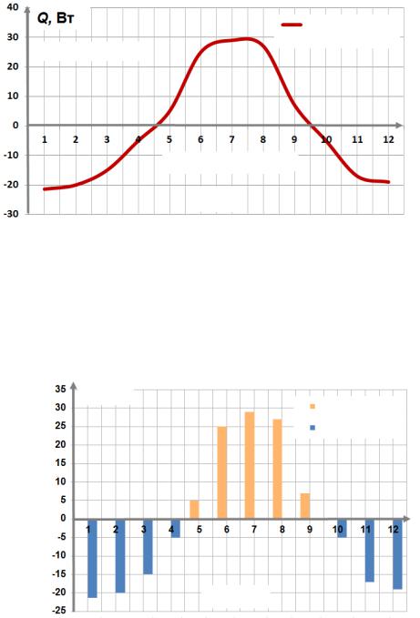
150m2 which provides engineering systems (air conditioning, heating, hot water), the number of residents is 5 people. According to the original data, the calculation of the required heat loads is made, the schedule of annual active loads is designed (Fig. 1).
46
Issue № 2 (50), 2021 |
ISSN 2542-0526 |
|
|
|
|
|
|
Q, Watt |
|
||
|
|
Annual active |
||
|
|
|
|
|
|
|
|
|
load on the object |
|
Heat supply |
|
||
|
|
|
||
|
||||
|
|
|
|
|
КондиционированиеConditioning
Month
Fig. 1. Schedule of annual active loads on engineering systems for the designed apartment house
The curve of active loads (Fig. 1) can be substituted by discrete sections equal in area to the actual ones, as the projected objects are generally thought of as enlarged indicators (Fig. 2).
Q, Watt
Heat supply
Heat dissipation
Month
Fig. 2. Averaged annual load
In order to identify the amount of heat supplied to the vertical well in the summer season and dissipated during the heating period, a new quantitative characteristic was introduced, i.e., the regeneration coefficient [15]. It is given by formula (1) using the obtained active averaged loads:
kр = |
Qsupply |
, |
(1) |
|
|||
|
Qdissipation |
|
|
47

Russian Journal of Building Construction and Architecture
where Qsupply is the amount of flow in the warm period of the year, Watt/m2; Qdissipation is the amount of dissipated flow in the cold period of the year, Watt/m2.
The efficiency of the heat pump depends on the temperature of the low-potential energy source. The criterion dependences [16] are set forth which allow one to calculate the predicted values of temperatures at the bottom of the well during the operation of the heat pump in different modes:
–– only for heat supply:
= 5 10 9 Q Fo2 + 2 10 8Fo Q + 0.0003 Q + 5.1, |
(2) |
where Fo is the Fourier test, Θ is the dimensionless temperature, Q is a relative thermal flow; –– with seasonal changes from heat supply to air conditioning and the other way around:
= 5 10 9 Q Fo2 + 2 10 8Fo Q + 0.0003 Q + 5.1(0.0004 kp + 0.947), |
(3) |
where Fo is the Fourier test, Θ is the dimensionless temperature, Q is a relative thermal flow, kр is the regeneration coefficient;
–– considering the effect of the groundwater:
= ( 5 10 9 Q Fo2 + 2 10 8Fo Q + 0.0003 Q + |
(4) |
|
5.1 (0.0004 kp + 0.947)) ( 0.0005 С+ 0.79) |
||
|
where Fo is the Fourier test, Θ is the dimensionless temperature, Q s a relative thermal flow, kр the regeneration coefficient, C is the water exchange criterion.
In order to convert the obtained dimensionless temperature into the actual one, equation (5) is used:
twell = ((tbackground tav.ос ) )+tav.ос , |
(5) |
where t of the well is the temperature of the wall of the well at the moment of the finish of the operated period in question, ºС; tср.ос is the average annual climatic temperature of the environment, ºС; tbackground is the background temperature of the soil, ºС; Θ is the dimensionless temperature.
The next stage of the design methodology includes calculating the design features of wells
[15––16] and their number. |
|
For this, let us calculate the total length of the well (6): |
|
L = Qо/q, |
(6) |
where Qо is the load on the heat supply system (or air conditioning) based on the heat balance calculations, Watt; q is the amount of heat removed from the surface layer of the soil, Watt/m2;
48
Issue № 2 (50), 2021 |
ISSN 2542-0526 |
The number of wells should be calculated in the following way (7):
ndesign = |
L |
, |
(7) |
|
|||
well |
lspecific |
|
|
|
|
||
where L is the design length of the well, m; lspecific is the specific length of the well adopted by assemblying organizations, m (in the range of 75––150).
Then the number of wells is adjusted considering the regeneration coefficient (8):
n |
= ndesign k |
р |
, |
(8) |
wells |
wells |
|
|
where nwelldesign is the deisgn number of wells; kр is the regeneration coefficient.
The capacity of the heat pump unit is defined by means of the conversion factor. It depends on the temperature difference between the RES and the consumer, as well as on the operating conditions. As the temperature of a low-potential energy source changes, so does the transformation coefficient. Fig. 3 shows a graph of the dependence of the change of the conversion factor on time and operation mode.
With regeneration
Without regeneration — conditioning
Without regeneration — heat supply
Year
Fig. 3. Graph of the dependence of the change of the conversion factor on the time and operation mode
Due to the changes of thermal processes during the operation of the heat pump and the operation of the RES, there is a regeneration of the soil mass. Let us note the positive effect of the regeneration effect itself and the regeneration coefficient on the low-potential energy source (Fig. 3).
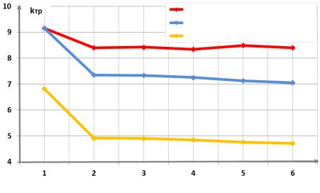
The next stage of the design methodology includes calculating technical and economic indicators and economic efficiency. Fig. 4 shows a graph of the dependence of the consumed thermal energy (Q) on the conversion factor (ktr) for different numbers of wells.
49