

Апсе ENVIRONMENTAL PROTECTION 2014
.pdfup to trivalent state and transferred into the aqueous fraction. Plutonium is separated from uranium.
4. Re-extraction of uranium from the organic fraction by diluted nitric acid. Uranium transfers into the aqueous fraction.
No more than three cycles of the extraction – re-ex traction process are traditionally used. The number of the cycles can substantially change the content of radioactive fission products in the reprocessed fuel materials, i.e. proliferation-resistance of the extracted plutonium can be changed. If the extracted plutonium is remarkably contaminated with radioactive and heat-generating fission products, then plutonium becomes unsuitable material for manufacturing of a weapon-grade nuclear explosive device. The low number of the extraction – re-extraction cycles well corresponds with the “dirty fuel – clea n waste” concept.
Specific features in reprocessing of spent fuel assemblies discharged from fast reactors. Spent nuclear fuel discharged from fast reactors (SNF-FR) is characterized by the higher values of fuel burn-up in comparison with spent nuclear fuel discharged from thermal reactors (SNFTR). In fast reactors fuel burn-up can reach 100 GWd/t HM via 40-50
GWd/t HM in thermal reactors. As a consequence, SNF-FR contains the larger quantities of plutonium (up to 20% via 0,7% in SNF-TR) and
fission products (up to 10% via 4-5% in SNF-TR). That is why SNF-FR reprocessing encounters the following technological challenges:
1.The more intense radiolysis of the SNF solutions and organic extractants.
2.The larger content of volatile fission products (I, Kr, Xe, T) requires applying the advanced gas-absorption systems at SNF chopping and dissolving.
3.The larger plutonium content can degrade TBP efficiency due to the lower solubility of plutonium dioxide.
4.The more intense radioactivity requires applying the advanced systems for remote control of the extraction – re-extr action process.
5.Volumes of liquid high-level wastes (HLW) are about five times larger than those released in the SNF-TR reprocessing. Nearly 10 m3 HLW per one SNF ton are produced in the SNF-FR reprocessing via 1-
3m3 HLW per one SNF ton in the SNF-TR reprocessing.
91
1.6. Treatment and ultimate disposal of radioactive wastes
All nuclear technologies are related with use or generation of radioactive substances. For example, fresh fuel assemblies of nuclear reactors contain radioactive isotopes of uranium; spent fuel assemblies contain radioactive isotopes of uranium, plutonium, transuranium elements and fission products. Some radioactive isotopes can be recovered from spent fuel and profitably used. Fissile isotopes can be repeatedly used (recycled) in fresh fuel compositions. Some fission products and transuranium elements are widely applied as heat sources, sources of ionizing radiation in medicine and various industrial branches. The remaining radioactive substances, whose profitable applications are unfeasible yet, are usually regarded as radioactive wastes (RAW). Thus, RAW are those radioactive substances whose profitable applications are unfeasible now.
Therefore, the following materials and products can be included into RAW composition:
1.Those products of nuclear technologies which are unsuitable now for any profitable applications.
2.All the materials and products which are contaminated with radioactive substances before their decontamination.
Specific peculiarity of RAW is a principal impossibility of their extermination by means of any traditional technology (incineration, conversion into any other chemical form). RAW remain to be radioactive in any chemical forms. Traditional technologies can only transform RAW into the forms suitable for ultimate disposal in deep underground geological repositories. Non-traditional methods of RAW extermination presume construction of the dedicated nuclear facilities where RAW are bombarded by ionizing radiation (neutrons or gamma-rays) with the only aim to transmute (convert) long-lived radioisotopes into short-lived or stable isotopes.
The most dangerous RAW are by-products of spent fuel reprocessing. These RAW are dangerous materials both in respect of their quantity and intensity of radiation emitted mainly by fission products. FP quantity in SNF discharged from thermal and fast reactors are equal to about 40-50 kg/t and up to 100 kg/t, respectively. Appropriate specific
92
radioactivities of SNF discharged from thermal and fast reactors are equal to ~6 MCi/t and 20 MCi/t, respectively.
For comparison:
1.Total release of radioactive materials after Chernobyl accident is evaluated as 90 MCi.
2.Total release of radioactive materials after Kyshtym accident (explosion of liquid RAW storage) is evaluated as 20 MCi.
1.6.1. Classification of RAW
Classification of radioactive wastes
RAW are classified depending on their state of aggregation (liquid, gaseous and solid RAW) and on their specific radioactivity (low-level, middle-level and high-level RAW). The norms used by Russian regulatory bodies for classification of RAW are presented in Tables 1.7, 1.8.
Table 1.7
Classification of liquid and gaseous RAW
|
Category |
|
|
|
Specific activity, Ci/l |
|
|
|||
|
|
Liquid |
|
|
Gaseous |
|
||||
|
|
|
|
|
|
|||||
|
Low-level |
|
£ 10-5 |
|
|
£ 10-13 |
|
|||
|
Middle-level |
|
10-5 – 1 |
|
|
10 -13 - 10-9 |
|
|||
|
High-level |
|
|
> 1 |
|
|
> 10-9 |
|
||
|
|
|
|
|
|
|
|
|
Table 1.8 |
|
|
|
Classification of solid RAW |
|
|
||||||
|
|
|
|
|
|
|
|
|
||
|
Category |
Dose |
|
|
|
Type of radiation |
|
|||
|
rate, R/h |
|
a, Ci/kg |
|
|
b, Ci/kg |
g, Gr/h |
|
||
|
|
|
|
|
|
|||||
|
Low-level |
< 0,2 |
|
|
2×10⁻⁷-10-5 |
2×10⁻⁶-10-4 |
3×10⁻⁷- |
|
||
|
|
|
|
|
|
|
|
3×10⁻⁴ |
|
|
|
|
|
|
|
|
|
|
|
|
|
|
Middle-level |
0,2-2 |
|
|
10-5-10-2 |
|
10-4-10-1 |
3×10⁻⁴-10-2 |
|
|
|
High-level |
> 2 |
|
|
> 10-2 |
|
> 10-1 |
> 10-2 |
|
|
93
Main mission of RAW treatment is to protect humans and the environment against negative effects of radioactive materials. The most significant negative effects include ionizing radiation, heat generation and chemical toxicity.
1.6.2. Treatment of high-level RAW
There are the following two main forms of HLW:
1. HLW from radiochemical SNF reprocessing facilities.
These wastes are mainly liquid RAW because the industrial-scale SNF reprocessing is primarily based on the aqueous solvent-extraction PUREX-like technologies. As is known, the solvent-extraction reprocessing of SNF discharged from nuclear power reactors can produce about 45 m3 of liquid HLW, 150 m3 of liquid middle-level wastes (MLW) and up to 2000 m3 of liquid low-level wastes (LLW) per one ton of spent fuel.
2. Spent fuel assemblies discharged from nuclear power reactors.
In the USA, where the moratorium has been decreed on radiochemical reprocessing of spent fuel from commercial NPP, these assemblies are considered as a form of the transport RAW containers completely ready for interim storage and, further, for ultimate disposal in deep underground geological repositories.
Main stages of the HLW treatment
1.Interim storage:
a.Spent fuel assemblies are placed into the water storage pools at NPP or at SNF reprocessing plants.
b.Liquid HLW are poured into the steel storage tanks. The storage tanks are put under strict control of heat generation rate (if necessary, forced heat removal must be provided) and elemental composition of the gas cushion over the HLW level (if necessary, air blowing-through is carried out to remove explosive hydrogen produced by water radiolysis).
2.Evaporation of liquid HLW.
The HLW evaporation process provides 200-fold reduction of the HLW volume. However, the following negative effects arise:
a. Specific radioactivity of the evaporated HLW increases.
94
b.Specific heat generation rate of the evaporated HLW increases too. The larger heat generation rate warms up the evaporated HLW.
c.Corrosion activity of the evaporated HLW intensifies due to the higher corrodent concentrations and to the elevated temperature.
d.Gas release intensifies too due to the radiolysis of water and some liquid HLW components.
The following countermeasures are usually undertaken:
a.Control of explosive hydrogen content in the gas cushion above the HLW level in the storage tanks.
b.Periodical air blowing-through for dilution and removal of explosive hydrogen.
c.Control of the gas cushion temperature (< 600С).
d.Forced heat removal.
e.Application of corrosion-resistant alloys and stainless steels as structural materials of the HLW evaporation facilities and the HLW storage tanks.
f.Introduction of the corrosion inhibitors into the evaporated HLW.
g.Disposition of the HLW storage tanks below the earth level on the concrete saucers.
3.Solidification of the evaporated HLW.
Main mission of the HLW solidification is to implant the HLW into a stable inert material (matrix) that can reliably prevent the HLW release into the environment and, finally, into the food chains. Migration ability of the HLW must be substantially weakened, or a reliable HLW immobilization must be guaranteed.
At present, the HLW implantation into some glass compositions, or the HLW vitrification, is considered as the most suitable form for the HLW immobilization. The following two technologies of the HLW vitrification are the most well-known:
1. One-step technology.
The liquid concentrated HLW are poured into a refractory crucible together with the glass-producing additives. Under gradual warming up, the mixture undergoes the following changes:
a.Ultimate HLW evaporation.
b.Calcination of dried HLW at 300-4000С.
c.Glass-mass melting at 1100-11500С.
95
After relatively short cooldown, the crucible with all its content is transported to the ultimate disposal site.
2.Two-step technology.
The French AVM-process can be considered as a typical example of the two-step HLW vitrification technologies.
Main stages of the AVM-process:
a.Calcination of the evaporated HLW at 300-4000С.
b.Mixing the calcination product with the glass-producing additives.
c.The mixture is poured into a melting furnace.
d.Gradual warming up and formation of the glass-mass at 110011500С.
e.Periodical drainage of the glass-mass into steel containers.
f.Interim storage and ultimate disposal of the HLW containers.
Some alternative versions of the HLW vitrification technologies have been developed till now. The alternative technologies presume the HLW implantation into other stable materials, such as ceramics, glassceramics or mineral-like SYNROC materials. The term SYNROC is an abbreviated form from the words “Synthetic Rocks”, i.e. artificial but natural rock-like materials. Development of the SYNROC materials and the technology for the HLW implantation into them (the SYNROC technology) is based on the hope that the SYNROC materials could be characterized by the same physical and chemical properties (primarily, high long-term stability) as their natural analogues.
The SYNROC technology includes the following main stages:
1.Mixing the evaporated HLW with predecessors of the SYNROC materials. These predecessors are, as a rule, various refractory oxides. One typical example of the SYNROC predecessor composition is as follows: TiO2(71%), CaO(11%), ZrO2(7%), BaO(6%), Al2O3(5%).
2.Calcination of the mixture at 650-7500С.
3.Hot pressing of the mixed powder into the SYNROC pellets (temperature - 1100-12000С, pressure - 150-200 atmospheres).
4.Filling up the steel containers with the SYNROC pellets, interim storage and ultimate disposal of the HLW containers.
Multiple tests were carried out with the HLW-containing SYNROC materials, and the following main results were obtained:
1. Physical, chemical and corrosion-resistance properties of the SYNROC materials appeared to be very similar with those of natural
96
rock minerals, i.e. the SYNROC materials are able to maintain their stability under any environmental impacts for sufficiently long time periods.
2.The SYNROC materials can retain up to 20% HLW.
3.The water-leaching rate of the SYNROC materials covered the range of 10-6÷10 -5 gram from 1 cm2 of the sample surface a day (g/cm2·day).
The achievable HLW contents and the HLW leaching rates from the SYNROC materials are inferior to analogous properties of the borosilicate glass. The borosilicate glasses can retain up to 30% HLW. In general, the glasses are characterized by intrinsically disordered molecular lattice and, therefore, the glasses are able to keep wide spectrum of various radioisotopes. The SYNROC materials with their finely ordered crystalline lattice are able to keep only the radioisotope compounds
with certain atomic dimensions and with certain valencies. The waterleaching rate of the vitrified HLW is evaluated as 10-8÷10 -7 g/cm2·day.
So, the SYNROC materials are inferior only to the glasses in respect to the achievable HLW content and the water-leaching rate but, nevertheless, they remain to be the second candidate for the HLW immobilization.
After the HLW are immobilized in the glass-mass or in the SYNROC pellets, these solidified HLW forms are placed into the steel containers. The further HLW management foresees sufficiently long (up to 50 years) interim storage in the near-to-surface storage points with air or water cooling. The containers can be periodically retrieved to investigate the current state of the solidified HLW and, if necessary, to perform their additional treatment.
1.6.3. Ultimate disposal of high-level RAW in geological formations
The next stage is an ultimate disposal of the HLW containers in deep underground geological repositories. Geological formation can be regarded as a suitable place for ultimate disposal of the HLW containers only if the formation satisfies the following requirements:
1.Geographical properties of the formation:
a.Far distance from the densely populated areas.
b.Low seismicity and low probability of earthquakes.
c.Far distance from the level of ground waters.
97
d. The geological stratum must not enter the earth surface.
2.Physical properties of the formation:
a.Good heat conductivity and heat capacity.
b.Good mechanical strength and plasticity.
c.Good chemical stability and retentivity of radioisotopes.
The following three geological formations are estimated now as the most promising candidates for ultimate disposal of the HLW containers in deep underground repositories:
1.Salt mines.
2.Sedimentary clayey formations.
3.Rocky formations.
Unfortunately, it appeared impossible to distinguish one the most suitable geological formation from these candidatures even basing only on their physical properties. All the candidates are characterized by their own advantages and drawbacks.
Salt mines
Advantages:
1.Far distance from ground waters, i.e. hydrological conditions of the salt mines were so stable that the salts remained in their initial state for a geological-scale time period (some millions or even milliards of years) despite of their good solubility by light water.
2.Good plasticity.
3.High heat conductivity.
Drawbacks:
1.Good solubility by light water.
2.Potential usefulness for many industrial branches.
3.Radiolysis by ionizing radiations with intense release of harmful gaseous substance (chlorine, for instance).
Sedimentary clayey formations
Advantages:
1.Full water impermeability.
2.High retentivity of radioactive fission products (with the exception of
129I and 99Tc).
3. Good plasticity.
Drawbacks:
1.Low retentivity of 129I and 99Tc, radioisotopes with high migration ability.
98
2.Low heat conductivity.
3.Proximity to the earth surface.
Rocky formations
Advantages:
1.High water impermeability.
2.Good mechanical strength and chemical stability.
Drawbacks:
1.Low plasticity, i.e. high probability for the cracks to appear as potential pathways for the HLW migration into the biosphere.
2.Low heat conductivity.
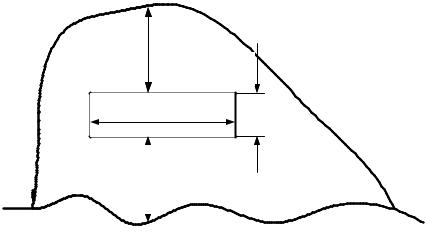
The most advanced all over the world project of the deep underground HLW repository is the Yucca Mountain project (Nevada, USA). Schematic layout of the Yucca Mountain repository is shown in Fig.
300 мm |
м |
|
7.6 |
7900 мm |
|
|
7.6 m |
|
200 мm |
|
||
|
|
|
|
|
|
|
|
|
|
|
|
LevelУровеньof groundгрунтовыхwaterвод
Fig. 1.8. Layout of the Yucca Mountain repository
Construction of the Yucca Mountain repository was begun in 1994. By April 1997 the main drifting works were finished with the following dimensions of the major tunnel: length – 7900 m; he ight – 7,6 m; distance from the level of ground water – 200 m downwa rds; distance from the mountain top – 300 m upwards. About $20 milliar ds were already
99
spent for these drifting works. In 2002 all the studies on geological, hydrological, geochemical and geothermal properties of the repository site were completed, and the US Nuclear Regulatory Commission received the application on start-up of the repository operation. As was previously planned, the loading process of the repository with the HLW containers must be begun in 2010 (total capacity of the Yucca Mountain repository was evaluated as 77,000 t HLW). However, the license on the repository operation was not issued by the NRC till now. Moreover, federal funding of the Yucca Mountain project was ended just in 2010.
The geological formation of the Yucca Mountain repository is a rocky tuff with large quantity of cracks. Vertical infiltration of light water from upwards into the major tunnel was measured and appeared equal to approximately one liter per one square meter of the tunnel bottom annually, i.e. 1 mm-thick water layer a year.
Some numerical evaluations demonstrated that major effect on potential contacts of ground water with radioisotopes and probability of their release into the biosphere from the fully loaded HLW repository Yucca Mountain is mainly defined by residual heat generation. The mountain part adjacent to the major tunnel can be warmed up to 1300С, i.e. above boiling temperature of ground water. So intense warming up can create the closed circuit of natural water convection from hot HLW repository to relatively cold rocks. There, water vapor condenses and flows down. That is why hydrological conditions of fully loaded repository cardinally differ from those in empty repository.
The following changes can occur in hydrological conditions of the fully loaded HLW repository:
1.Formation of the condensed water layer above the HLW repository by natural convection of hot vapor and cold water.
2.The rocky area adjacent to the HLW repository is impregnated with water.
3.Intense cracking of the tuff layers adjacent to the HLW repository by hot vapor and temperature gradient.
4.Chemical activity of hot water enhances. Consequently, corrosion rate of the HLW containers and solubility of radioisotopes can increase.
Central zone of the HLW repository can remain relatively dry because of maximal heat generation rate and rapid evaporation of the flowing down water. Atmosphere in peripheral zone of the HLW re-
100