

ИЭ / 6 семестр (англ) / Лаба / Homework_1_(Electrostatics)_What_to_do
.pdf21
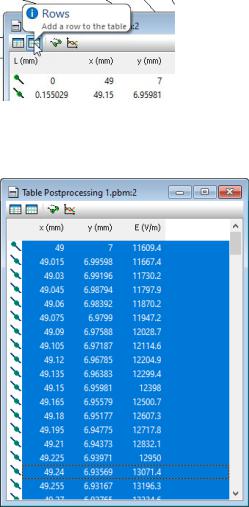
Click the Columns button and left only three columns to show: x, y, and E
Then click the Rows button and ask to tabulate the contour with 200 segments (201 points)
In the table select all rows and column captions by pressing Ctrl+A keys (Select All Rows command) and drag the contents of the table to your favorite table processor, e.g. Excel
Now you can sort the table by the E value from largest to smallest values, and the first row in your table will contain the maximal field value along with the point coordinates. Put it to your report together with corresponding mesh spacing value on the rounded capacitor corner. Repeat this with decreased values of the mesh spacing until you reach the convergency with accuracy <1%.
22
2.9.EXTRACT LOCAL FIELD VALUES
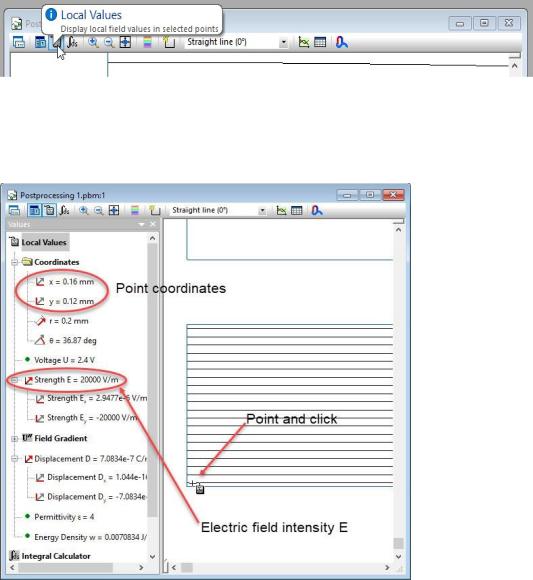
Besides various field pictures you can extract from the solution a value of different physical quantities, both local and integral. The Local field quantities describe the field in a given point. Locals include: electric field E (magnitude and components), electric displacement D, potential U and some others.
To extract a local value, click the Local Values button on the postprocessor’s toolbar
,
And then click the point you want to know field values in the field picture window.
To extract integral quantities, you first have to define the domain of integration. QuickField can calculate integrals:
23

1. over a line L, for example, potential difference U = E dl
L
2. over a surface S, for example, electric flux q = D ds
L
3. over a volume V, for example energy of electric field W = 1 D E dv
2 V
In all cases the domain of integration is given by a plane contour that can be open or closed.
•An open contour defines a line and a side surface,
•A closed contour defines a line and two surfaces – a side surface and a cross-section surface in the model plane, as well as a volume inside the closed surface.
2.10.CALCULATE THE CAPACITANCE
The capacitance can be calculated in the following ways:
1.Using the definition, as a ratio of the charge to the voltage difference: Cq = qU
2.By electric field energy: Cw = 2UW2
In both cases we have to calculate an integral value:
•the electric charge as q = D ds
L
• the total electric field energy in the model: W = 1 D E dv
2 V
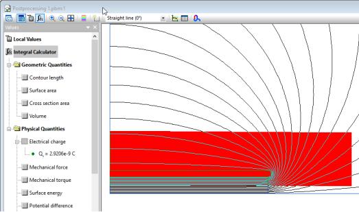
One of the ways to calculate the electric charge of a capacitor plate is to use the Gauss theorem. The charge is calculated as an electric flux other any closed surface surrounding the conductor. For numerical reasons to achieve better accuracy is recommended to draw the contour far enough from the region where the field changes quickly, e.g. as shown in the picture below:
24
The domain of integration for the electric field energy is the total volume of the model. To define such domain, one must enter the contour defining mode (click the Add to Contour button on the postprocessor toolbar), and then click all the model blocks one by one.
QuickField also provide a tool simplifying the capacitance calculation – the Capacitance wizard.
25
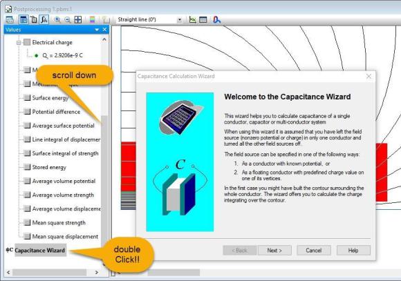
Anyway, before starting the Capacitance wizard you have to define the contour for charge integration as described above.
Next to the introductory page the Capacitance wizard offers a window for choosing the conductor of interest
26
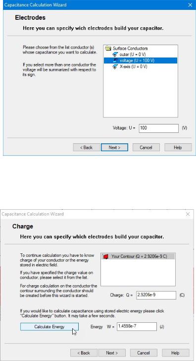
,
On the next page we have to click the contour in the list on the top and press the button Calculate Energy. As result both integrals needed for capacitance – the charge and the energy, gets calculated.
Click the Next button leads to the results page:
27
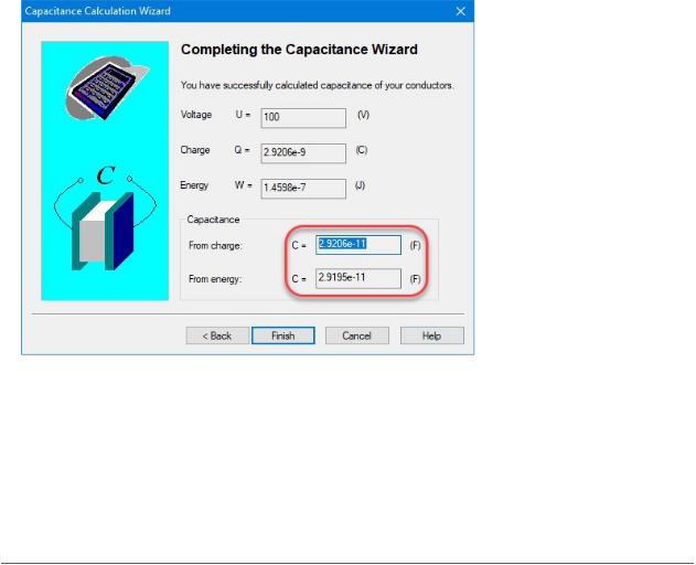
Ideally both capacitance values calculated by charge and by energy should be very close to each other. The significant difference may indicate a methodical error. Because the mode employs symmetry it is a good idea to think about possible symmetry factor.
3. REPORT CONTENT
Please start your report with a cover page containing your name and group number, the project name, and the current year.
The report may be organized in the following way:
Report content:
1.Task description and the given data
2.Sketch of the geometry model with no mesh
3.Dependency of maximal field Emax on the mesh spacing on the rounded capacitor’s corner.
Please provide at least 5 points up to the convergency of EMAX = f(spacing). The dependency should be presented in the form of a table and an XY-plot.
4.Pictures with the mesh and E-field around the rounded end of the conductor:
4.1With the initial (automatic) mesh spacing
4.2With the final mesh spacing
5.Choose an optimal mesh spacing on the conductor from the previous research and investigate the dependency of EMAX on the radius R0 of the artificial outer boundary until the convergency
28

is achieved. Start with the small radius, e.g., twice the half-width of the conductor, and continue increasing it while the field EMAX keeps changing.
6.The rest of calculation please do only once with the final mesh spacing and the final value of the radius R0.
7.Calculate the capacitance:
-Cth by a simple formula (theory of a plane capacitor)
-Cq using charge
-Cw using energy
8.Calculate the field in the middle of capacitor Ec
9.Please submit your work by email to sdubitsky@gmail.com . Include your report (Word or PDF) and all QuickField files related to the final mesh density and final position of the outer boundary.
4.FINAL DEFENSE
Please be prepared to explain how and why you have set up the boundary conditions, especially the boundary conditions due to symmetry.
You may be asked to explain in detail how you do the integration for charge and energy, including what is the domain of integration and what formula was used.
Think about possible symmetry factor to jump from the one quarter to the entire model.
An additional question you may be asked is how to calculate the mechanical force acting on the capacitor’s plate.
29