

Scientific Herald of the Voronezh State University of Architecture and Civil Engineering Construction and Architecture
.pdfIssue № 4(32), 2016 |
ISSN 2075-0811 |
Fig. 3. Vector field of the speeds of the air flows during the vertical-bottom air supply with flat flows
Fig. 4. Speed of the air flows. Changes range from 0 to 0,5555 m/seс
Fig. 5. Speed of the turbulent kinetic energy of air flows. Changes range from 0 to 0,0164 m2/sec2
Along the walls of the premise there is invariably a low-speed upcoming air flow directed to
the areas of the air removal in the upper part of the premise.
21
Scientific Herald of the Voronezh State University of Architecture and Civil Engineering. Construction and Architecture
Fig. 6. Current lines of air flows
The comparison of different options for inlet air supply showed that the use of flat and nonflat fan flows at the angle of aperture of the flow of 45 and vertical-bottom air supply give a similar insight into the distribution of air flows and air speeds in the premises as well as in the working area.
In actual premises flows of inlet air from the air distributors are restricted by building structures and technological equipment. The air around the flows is not “still” but moves forward. As a result, the profile of the speeds of the flows is greatly deformed. The speed of the air in the axes of the flows depends on the type of an air distributor at the distances of 4 m away from the air distributor. At larger distances from an air distributors the air speed in the axes of the flows does not significantly depend on the type of an air distributor.
The most effective was the option with inlet air supply with vertical-bottom flat flows along the centre of the premise and at the angle of 20 to the vertical along the sides of the premise. The clean air is supplied into the working areas and it is only after this that it enters the area of local suctions. Upcoming flows are over the baths and transfer harmful substances from the working area into the upper part of the premise.
Conclusions
The mathematical model of the air distribution in the premise was developed using the discontinuity equation, the system of the Reynolds averaged Navier-Stokes equations and equations of k- turbulence models.
The analysis of the results of the calculations for different options of the inlet air supply sows that during the interaction of the inlet air from air distributors with building constructions and local suctions flows are greatly deformed.
The use of flat and incomplete fan flows at the angle of aperture of a flow of 45 and verticalbottom air supply give a similar insight into the distribution of air flows and do not allow an
22
Issue № 4(32), 2016 |
ISSN 2075-0811 |
effective air exchange as clean air is removed with local suctions and thus does not enter the working area.
The most effective is an air exchange scheme with the inlet air supply with vertical-bottom flat flows along the centre of the premise and at the angle of 20 to the vertical along the sides of the premise. Clean air enters the working area and it is only after it does that it is removed by local suctions. Upcoming flows are over the baths and transfer harmful substances from the working area into the upper part of the premise.
The suggested method allows one to calculate and select a system of air flows in the premise that most effectively uses the inlet air and to enhance the efficiency of ventilation with no extra costs.
References
1.Mel'kumov V. N., Kuznetsov S. N., Cheremisin A. V., Sklyarov K. A. Nestatsionarnye protsessy formirovaniya sistemami ventilyatsii vozdushnykh potokov v pomeshcheniyakh [Nonstationary processes of the formation of the ventilation air flow in rooms]. Izvestiya Orlovskogo gos. tekhn. un-ta. Stroitel'stvo i transport, 2007, no. 3––15, pp. 36––42.
2.Mel'kumov V. N., Kuznetsov S. N., Pavlyukov S. P., Cheremisin A. V. Nestatsionarnoe pole kontsentratsiy prirodnogo gaza v skvazhine pri ego utechke iz podzemnogo gazoprovoda [Nonstationary field of concentration of natural gas in the well in a leakage of underground pipeline]. Privolzhskiy nauchnyy zhurnal, 2008, no. 4, pp. 98––103.
3.Mel'kumov V.N., Kuznetsov I. S., Guseva L. Yu., Cheremisin A. V. Otsenka akkumuliruyushchey sposobnosti ventiliruemykh ob"emov dlya snizheniya trebuemogo vozdukhoobmena v pomeshcheniyakh [Evaluation of the accumulating capacity of the vented volume to reduce the required air exchange in premises].
Vestnik Voronezh. gos. tekhn. un-ta, 2007, vol. 3, no. 1, pp. 205––207.
4.Mel'kumov V. N., Kuznetsov S. N., Pavlyukov S. P., Kuznetsov R. N. Formirovanie konvektivnykh vozdushnykh potokov pri deystvii v pomeshchenii istochnika tepla [Formation of convective air flow under the action of indoor heat source]. Vestnik Volgograd. gos. arkh.-stroit. un-ta. Stroitel'stvo i arkhitektura, 2008, no. 12, pp. 76––80.
5.Mel'kumov V. N., Lapin V. A., Kobelev A. N. Osobennosti teplomassoobmena potoka dvukhfaznogo teplonositelya na lopasti vikhrevogo zavikhritelya [Peculiarities of heat and mass transfer two-phase flow of the coolant on the blade vortex swirler]. Nauchnyy vestnik Voronezhskogo GASU. Stroitel'stvo i arkhitektura, 2008, no. 2, pp. 119––124.
6.Mel'kumov V. N., Kuznetsov S. N. Dinamika formirovaniya vozdushnykh potokov i poley temperatur v pomeshchenii [Dynamics of formation of air streams and temperatures fields in premise]. Nauchnyy vestnik Voronezhskogo GASU. Stroitel'stvo i arkhitektura, 2008, no. 4, pp. 172––178.
7.Mel'kumov V. N., Kuznetsov S. N. Vzaimodeystvie ventilyatsionnykh vozdushnykh potokov s konvektivnymi potokami ot istochnikov teploty [The interaction of ventilation air flows with convection flows from heat sources]. Izvestiya vuzov. Stroitel'stvo, 2009, no. 1, pp. 63––70.
8.Kuznetsov S. N., Sklyarov K. A., Cheremisin A. V. Modelirovanie rasprostraneniya vrednykh veshchestv v soobshchayushchikhsya pomeshcheniyakh [Modelling of distribution of harmful substances in the communicating areas]. Nauchnyy vestnik Voronezhskogo GASU. Stroitel'stvo i arkhitektura, 2008, no. 1, pp. 108––112.
23

Scientific Herald of the Voronezh State University of Architecture and Civil Engineering. Construction and Architecture
9.Mel'kumov V. N., Kuznetsov S. N., Pavlyukov S. P., Cheremisin A. V. Prognozirovanie fil'tratsii gaza v grunte pri ego utechke iz podzemnogo gazoprovoda [Prediction of gas filtration in the soil when it leaks from an underground pipeline]. Izvestiya OrelGTU. Stroitel'stvo. Transport, 2008, no. 3/19(549), pp. 61––65.
10.Mel'kumov V. N., Kuznetsov S. N., Gulak V. V. Modelirovanie zadymlennosti pomeshcheniy slozhnoy konfiguratsii v nachal'noy stadii pozhara [Modeling of smoke content of premises of complex configuration at initial stage of fire]. Nauchnyy vestnik Voronezhskogo GASU. Stroitel'stvo i arkhitektura, 2010, no. 3(19), pp. 131––139.
11.Loboda A. V., Kuznetsov S. N. Ispol'zovanie metoda konformnykh otobrazheniy dlya opredeleniya poley skorostey vozdushnykh potokov v zadachakh ventilyatsii [Using the method of conformal mappings to determine velocity fields of air flows in ventilation tasks]. Nauchnyy vestnik Voronezhskogo GASU. Stroitel'stvo i arkhitektura, 2011, no. 1(21), pp. 15––22.
12.Pavlyukov S. P., Kuznetsova G. A., Kobelev A. N. Analiz sostava i prodolzhitel'nosti ekspluatatsii gazovogo oborudovaniya [Analysis of the composition and duration of operation of gas equipment]. Inzhenernye sistemy i sooruzheniya, 2012, no. 3(8), pp. 16––23.
13.Mel'kumov V. N., Kuznetsova G. A. Modelirovanie protsessa remonta vnutridomovogo gazovogo oborudovaniya [Modeling the repair process in-house gas equipment]. Nauchnyy vestnik Voronezhskogo GASU.
Stroitel'stvo i arkhitektura, 2013, no. 1(29), pp. 101––108.
14.Kuznetsov I. S., Kuznetsova G. A., Mkrtchyan A. G. Integrirovannye karty vliyayushchikh faktorov dlya vybora optimal'noy trassy avtomobil'noy dorogi [Integrated maps of influencing factors to select the optimal route of the road]. Inzhenernye sistemy i sooruzheniya, 2014, no. 2(15), pp. 67––72.
15.Kuznetsov I. S., Kuznetsova G. A., Mkrtchyan A. G. Algoritmy poiska optimal'noy trassy prokladki avtomobil'noy dorogi [Algorithms for finding the optimal way of laying of roads]. Inzhenernye sistemy i sooruzheniya, 2014, no. 2(15), pp. 73––79.
16.Awni Al., & Hamzeh D. Analysis of mechanical system ventilation performance in an atrium by consolidated model of fire and smoke transport simulation. International Journal of Heat and Technology, 2015, no. 30(3), pp. 121––126. doi: 10.18280/ijht.330318.
17.Shu K., Huang Y., Zhang S. Reasonable layout and numerical simulation of compound ventilation mode in power transformer room. Building Energy Efficiency, 2010, vol. 38, no. 1, pp. 34––38.
18.Juan C. R., Beiza M., Jon G., Rivas A., Raúl A., Larraona G. S., Miguel I. de. Numerical modeling of the natural ventilation of underground transformer substations. Applied Thermal Engineering, 2013, vol. 51, no. 1––
2, pp. 852––863.
19.Ramponi R., Blocken B. CFD simulation of cross-ventilation flow for different isolated building configurations: Validation with wind tunnel measurements and analysis of physical and numerical diffusion effects. Journal of Wind Engineering and Industrial Aerodynamics, 2012, vol. 104––106, pp. 408––418.
20.Ratnieks J., Jakovičs A., Gendelis S. Mathematical modelling of airflow velocity and temperature fields for experimental test houses. Proceedings of the 10th Nordic Symposium on Building Physics. Lund, Sweden, 15–19 June 2014, pp. 871––878.
24

Issue № 4(32), 2016 |
ISSN 2075-0811 |
UDC 536.24
L. A. Kushchev1, N. Yu. Nikulin2, A. Yu. Feoktistov3, E. A. Yakovlev4
INTENSIFICATION OF THERMAL PROCESSES
IN A SHELL-AND-TUBE HEAT EXCHANGER
Belgorod State Technological University Named after V. G. Shukhov Russia, Belgorod, tel.: +7-910-363-62-09, e-mail: Nick_973gt@mail.ru
1D. Sc. in Engineering, Prof. of Dept. of Heating and Ventilation 2PhD student of Dept. of Heating and Ventilation
3PhD in Engineering, Assoc. Prof. of Dept. of Heating and Ventilation
4PhD in Engineering, Assoc. Prof. of Dept. of Road and Railway Engineering
Statement of the problem. The article is devoted to a problem of intensification of thermal processes in the shell-and-tube heat exchanger by increasing turbulization of a heated fluid.
Results. The article presents the results of the theoretical research devoted to the intensification of a thermal processes in a shell-and-tube heat exchanger by increasing a heat-exchange surface and turbulization of the fluid flow. The computing experiment of flow turbulization on a flat plate with a circular section rib was performed on the basis of the “Ansys CFX” software package. The experiment gave an opportunity to define the optimal distance between the cylindrical ribs of heat-exchange surface.
Conclusions. As a result of the research, the method of an intensification of thermal processes in the shell-and-tube heat exchanger is suggested, which involves the selection of optimum distance between the cylindrical ribs.
Keywords: shell-and-tube heat exchanger, heat emission, hydrodynamics, fluid flow, streamline flow, turbulization, flat plate, cylindrical rib, graphic distribution.
Introduction
Heat exchangers are currently being commonly used in energetics, other industries as well as housing. Therefore the problem of improving this equipment to enhance its performance is tremendously important [2, 11, 18].
The major characteristics of a heat exchanger is a heat exchange coefficient k, Watt/(m К) that indicates how much thermal energy is transferred through a heat-exchange surface from a heating and heated contour. This depends on a heat transfer coefficient α, Watt/(m² К): the higher α is, the larger К [3, 6, 7]. Therefore in order to increase a heat transfer coefficient α, it is necessary to intensify heat exchange when a fluid flows along a heat-exchange surface.
© Kushchev L. А., Nikulin N. Yu., Feoktistova А. Yu., Yakovlev Ye. А., 2016
25

Scientific Herald of the Voronezh State University of Architecture and Civil Engineering. Construction and Architecture
There are two ways to intensify heat exchange –– the active and passive one.
The active methods involve extra external energy. Intensification is achieved by mixing fluids mechanically, e.g. with vibration or rolling of a heat-exchange surface.
Thus there is an increase in the speed of a fluid flow and a decrease in the thickness of an boundary layer. Heat exchange is also intensified by sound waves with the frequencies of from 1 Hz to the ultrasound. An electrical field has an influence as well as it causes forces accelerating convection [1, 2, 5, 16].
It should be noted that the active methods require extra equipment and energy. Thus such technical solutions make heat-exchangers energy-dependent.
The passive method involves a maximum decrease in the thickness of an boundary layer due to ribbed or other developed heat-exchange surfaces, spirally twisted heat-exchange tubes [1, 3, 6, 19].
There are also complex methods of intensifying heat exchange which involve a combination of methods in one heat exchanger (no less than two). For example, rough tubes with insertions swirling a flow, vibrating ribbed pipes, etc. [4, 18].
Intensification of heat exchange of a shell-and-tube heat exchange. A promising method of intensifying heat exchange is an artifical turbulization of a flow (passive). Hence according to A. A. Zhukauskas, for a cross flow over a tube due to turbulization, its average heat transfer can be increased by up to 55 %. Tube bundles for cross flow are intensified by studding of pipe surfaces. Cylindrical, cone-shaped, parabolic and drop-shaped studs are used for that. Roughness of tubes is used to a varying degree. As S.S. Kutatelladze indicated [9, 10], the intensification of heat exchange in this case is associated with failure of rough elements of a viscous sublayer for turbulent motion as well as an growing instability of an boundary layer. Then a transition from a laminar into a turbulent motion mode takes place on a rough surface for a smaller Re than on a smooth one.
An important construction solution for improving the intensification of heat exchange is selecting an optimal geometry of a heat exchange surface as the operation of equipment depends on it overall. In order to increase a heat transfer coefficient, it is most viable to use a variety of ribbed surfaces. A linear heat transfer coefficient k, Watt/(m К) through a round tube of a heat exchanger is given by
k |
|
|
|
1 |
|
|
|
|
, |
(1) |
|
|
|
|
|
|
|
|
|||
|
|
|
|
|
|
|
||||
|
1 |
|
1 |
|
1 |
|
|
|||
|
ln |
d2 |
|
|
|
|
||||
|
1d1 |
2 |
|
2d2 |
|
|||||
|
|
d1 |
|
|
||||||
26
Issue № 4(32), 2016 |
ISSN 2075-0811 |
where d1, d2 are the interior and exterior diameters of a heat-exchange tube, m; α1 is a heat transfer coefficient from a fluid, Watt/(m² К) flowing in a heat exchanger to the internal surface of a tube; α2 is a heat transfer coefficient of the exterior surface of a heat-exchange tube to a fluid, Watt/(m² К) washing a heat-exchange tube; λ is a heat exchange coefficient of a tube material.
It is necessary to increase the coefficients с and α2 are increased for a passive method of intensifying heat exchange. For artificial turbulization, as was shown above, an boundary layer decreases and the heat transfer coefficients α1 and α2 increase.
We suggest the use of a method of intensifying heat exchange in heat exchangers that involves flat heat exchange surfaces of cylindrical ribs to increase turbulization of a fluid flow. This will ultimately lead to an increase in the heat transfer coefficient of a heat-exchanger and decrease in the size of its structure.
Hydrodynamics of a fluid flow of a single rod. The papers [7, 19] look at a flow of a single rod of a rectangular section with the height of Н on flat plate and transverse washing of a single cylinder. A swirling area (towards a fluid flow) is known to form behind the rod and cylinder accompanied with turbulization. Its length is (6—12) N.
It seems viable to make use of a high turbulization area in order to destroy a laminar sublayer and increase the heat transfer coefficient α. Cylindrical ribs are supposed to be placed on a flat heat exchange surface (plate).
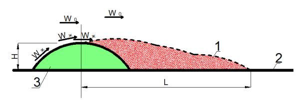
Fig. 1 shows washing of a heated flat heat-exchange surface (plate) with a fluid fitted with cylindrical ribs (Fig. 1).
Swirling area
Fig. 1. Development of a swirling motion of a fluid behind a clylindrical rib during washing: 1 is a swirling and mainly turbulized area;
Wж is a tangent speed during washing of the cylindrical ribs, m/seс;
W0 is the speed of the major fluid flow, m/seс
27
Scientific Herald of the Voronezh State University of Architecture and Civil Engineering. Construction and Architecture
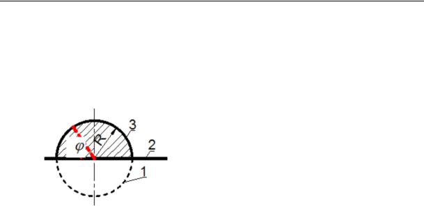
As a cylindrical rib is used for an artificial turbulization flow, there is a turbulent mode of a fluid motion (as well as in the space between the tubes of heat-exchangers in industrial operation) in studying washing of a rib with water and dealing with heat exchange. Let us look at a cylindrical rib (Fig. 2).
Fig. 2. Cylindrical rib of a heat-exchange surface:
1 is a cylinder (a transverse section);
2 is a plate;
3 is a cylindrical rib
In this case as a cylinder is washed in the turbulent mode, swirls already break away at
φ = 82° [7, 18]. At this particular area of the loom there is already a swirling area (Fig. 1), which is accompanied with a failure of a laminar sublayer of a flat plate. The length of this area of the plate is roughly (6—12) N where N is the height of a rib.
It should be noted that in the laminar sublayer heat is transferred from the wall to the fluid (or the other way around) using heat conductivity. The thicker is a laminar sublayer, the less heat it is capable of transferring. Thus a decrease in the thickness of a laminar sublayer of a fluid near a plate promotes the growth of heat transfer (an increase in the heat transfer coefficient) through this layer. The heat transfer coefficient from a plate to a fluid , Watt/(m²·°Sec) is known to be given by the formula
|
Nu |
, |
(2) |
|
l |
|
|
where λ is a heat coefficient of a body, Watt/(m·К); Nu is the Nusselt number; l is a determining geometric parameter of a surface (for a plate — length, m).
The Nusselt number Nu is calculated for a turbulent mode using the formula [12, 13]
Nu |
ж, l |
0, 037 Re0,8 |
l |
Pr0,43 |
(Pr |
/ Pr )0,25 |
, |
(3) |
|
ж, |
ж, l |
ж, l |
cn |
|
|
where Reж, l is the Reynolds number that increases during the turbulization of a fluid flow; Pr is the Prandtl number.
According to the formula (3), as the numbers Reж, l and Pr increase, so does the number Nuж, l, and according to the formula (2), as Nu increases, so does the heat transfer coefficient . Therefore in order to intensity heat transfer in a shell-and-tube heat exchanger, it is necessary that the turbulization of a fluid flow washing a heat-exchange surface is increased.
28
Issue № 4(32), 2016 |
ISSN 2075-0811 |
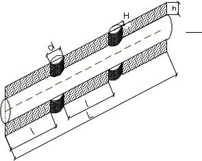
We set forth an original structure of a shell-and-tube heat exchanger with a flat heat-exchange surface where cylindrical ribs are placed (Fig. 3).
A computational experiment was conducted in looking at flowing of a flat plate with cylindrical ribs. The major goal was to determine an optimal step between the cylindrical ribs l at operational speed modes of the investigated heat exchanger identified in SP 41-101-95 “Design of Heat Spots”.
 D 10х1
  1
1
 2
2
 3
3
Fig. 3. Element of a heat-exchange surface of a shell-and-tube heat exchanger:
1 is a tube; 2 is a plate;
3 are cylindrical ribs
The study of changes in the turbulization on a flat plate with cylindrical ribs was performed using the Ansys CFX software. It is designed for a variety of calculations in hydrodynamics as well as a wider range of problems and detailed studies of processes involved in gas and liquid flow under different conditions (fluid flowing of curved surfaces, a palt surface, flowing of a fluid from a pipeline, etc.).
In order to model a fluid flow along a plate of a heat exchanger, the Mentler SST-model of shear stress recommended for calculating models with possible small flow delays. The SST- model relies on a linear combination of the Wilcox k-ω-model for near-surface areas and the k-ε-model away from surfaces [8, 21].
For the research the following construction parameters of elements of a heat-exchange surface of a shell-and-tube heat exchanger were employed: d = 8 mm, Н = 4 mm, h = 5 mm,
D = 10×1 mm, L = 1000 mm. The construction size l is a determined step of the position of cylindrical ribs (Fig. 3).
As was shown in [7], at the distance L from the centre of the ribs (6—12) N swirling motion grows less intense compared to the onset of the formation of a swirling area, which reduces the efficiency of heat transfer. Therefore it is important to identify the distance l when
29

Scientific Herald of the Voronezh State University of Architecture and Civil Engineering. Construction and Architecture
turbulization is sufficiently storng and place the next rib accordingly. It is essential as an extreme decrease in the distance between the ribs for high turbulization causes growing hydraulic resistance of a heat exchanger.
For the research the distance between the centres of the ribs is accepted to be 10 N (44 mm), then the distance between adjoining edges of the ribs is 36 mm.
The research took place under the viscous fluid conditions (water with the viscocity
= 1,002 mPа seс). The space of a fluid flow was restricted with a heat-exchange surface and a parallel plane.
According to SP 41-101-95 “Designing of Hot Spots”, the optimum speed of fluid in heat exchangers is 1 m/с. The speed of fluid under the operational conditions of heat exchangers of heat supply systems ranges between 0,3—1,1 m/sec. Therefore it was decided that the research is carried out in four modes of a fluid flow speed (during washing of a heat-exchange surface) — 0,1, 0,4, 0,7, 1 m/seс.
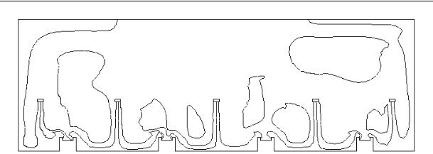
The results of a computational experiment using the Ansys software are presented as graphical representation of the distribution of intensity of turbulization at different speeds of transverse washing of cylindrical ribs with the step of 36 mm (Fig. 4).
Washing speed |
Diagram of the intensity of |
|
turbulization |
а) |
|
b)
c)
d)
Fig. 4. Graphic representation of the distribution of intensity of turbulization at different speeds of transverse washing of cylindrical ribs; speed of transverse washing — 0,1 m/seс (а), 0,4 m/seс (b), 0,7 m/seс (c), 1 m/seс (d)
30