

Учебное пособие 1862
.pdfList dialog box and from there lets you access other active Windows applications. CTRL + ESC may also be used.
The Circuit control menu in the upper left of the circuit window provides similar commands for the Circuit window.
Circuit control menu
Restore: This command restores the circuit window to its old size after it has been enlarged with the Maximize command or reduced to an icon with the Minimize command.
Move: This command lets you move the circuit window by using the cursor keys. Size: This command lets you resize the circuit window with the cursor keys. Minimize: This command minimizes the circuit window to icon size. Maximize: This command maximizes the circuit window to its maximum size. Close: This command closes the circuit window. CTRL+ F4 is also used. Next: This command switches to other circuit windows. CTRL + F6 also works.
Title bar: The title bar at the top center of the window shows the window name. Using the mouse, you drag the title bar to move the window. The window may also be moved with the keyboard using the move option from the Window menu. Cursor keys move a window outline and the ENTER key terminates the move.
Main tool bar: The Main tool bar, positioned below the title bar, contains buttons that represent frequently used menu options for all windows, providing a quick way to access these options. Clicking on a button will activate the option. The tool bar groups buttons into logical sets which can be placed at any of the four sides or can float above the schematic. To move a set, disable the Lock Tool Bar option in the Common Options section of the Preferences dialog box and drag the gray border around the tool set to the new location. Buttons for all major actions options are available. Buttons can be added or deleted from the Main Tool Bar section of the Preferences dialog box.
39
Local tool bar: The local tool bar, usually positioned below the main tool bar, contains buttons that represent frequently used menu options that are available in the local window. Like the main tool bar, tool sets can be moved to preferred locations. Docking of the entire local tool bar can be toggled between the left and the top simply double-clicking in the open area of the tool bar.
Maximize/minimize buttons: These buttons are in the upper right portion of the window. Clicking them maximizes, minimizes, or restores the window. The upper set of buttons control the MC6 window and the lower set controls the active circuit window.
Horizontal and vertical scroll bars: The scroll bars to the right and lower right of the window let you pan the screen horizontally or vertically. Clicking on the scroll arrows pans the display smoothly, at a rate of roughly 10% of the window width per click.
Horizontal and vertical splitters: These black bars can be dragged to split the display either vertically or horizontally. Split display sections have individual scroll control, letting you select widely separated areas for simultaneous viewing.
Flag button: There are several ways to navigate a schematic, including the right mouse button drag and shift-click relocation. Another method, called navigating flags, lets you place flags around the schematic and then provides an easy way of selecting them. The flag button is near the lower right corner of the window. Clicking this button invokes a list of schematic flags and lets you position the schematic view at the flag by clicking on a flag name in the list.
Page scroll bar controls: These controls include left and right page scroll buttons and first page and last page buttons. Clicking on one of the buttons scrolls the view of the page tabs in the direction of the button arrow.
Page selector tabs: These tabs let you select a page for display by clicking on its tab with the left mouse button. A right mouse button 40
click on a tab invokes a menu that lets you add a page, delete the tab page, or rename it. Clicking in the region between tabs invokes a button that lets you add pages. Pages can also be added or deleted from the Edit menu.
Page tab display width control: The width of the page tab display is controlled by dragging the Page tab width control left or right. This changes the proportion of the scroll bar allocated to the Page scroll bar versus the Horizontal scroll bar.
Status bar: This optional bar provides summary descriptions of the menu item or object currently under the mouse cursor, as well as other explanatory messages. Its display can be toggled on or off from the
Options menu.
Menus
The menus used by MC6 are selected in two ways:
Mouse menu selection: To select a menu item with the mouse, move the mouse to the menu and click somewhere on the menu name. The menu pops down, revealing a list of commands or options. Sometimes a submenu appears to the right disclosing further choices. Move the mouse to the desired option and click again.
Keyboard menu selection: To select a menu item with the keyboard, simultaneously press the ALT key and either the first letter of the menu name or the underscored letter if one is present. Then select the desired option from the menu by either pressing the first letter (or the underscored letter if one is present) of the option name, or use the UP ARROW or DOWN ARROW cursor keys until the desired option is selected and then press the ENTER key. Submenus are denoted by an arrow pointing to the right. To invoke a submenu, use either the RIGHT ARROW or ENTER key. To collapse a submenu, use the LEFT ARROW cursor key. The cursor keys may also be used to navigate through the activated menu and submenus.
41
Dialog boxes
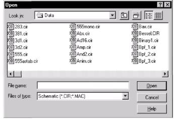
When you select options or enter data it is frequently done through a dialog box. Here, for example, is the Open dialog box for files:
Figure 2-17 The Open dialog box
Both the mouse and keyboard may be used for selection or data entry. The selected field will be highlighted or framed.
Using the keyboard: The TAB key is used to move among the fields. For text entry fields such as a file name, the data is simply typed in. The SPACEBAR is used to select the Open, Cancel, and Help options. For drop-down boxes or lists, the cursor keys may be used to scroll among the options. Type the first letter of the desired item to rapidly locate the group of items that begin with the letter. In the directories list, the ENTER key and cursor keys are used to change to a new directory. The TAB key moves through the fields in one direction and SHIFT + TAB moves in the opposite direction.
Using the mouse: Move the mouse to the desired field and click. For text entry fields such as a file name, the data is simply typed in.
42
For the Open, Cancel, and Help items, click the buttons to select the option. For drop-down boxes, click on the drop-down arrow, and then click on the desired selection. In the directories menu, double click on the directory icon to change to that directory.
The File menu
Ответьте на вопросы
1.Какие функциональные сочетания клавиш Вы знаете?
2.Объясните значение понятий Box, Step Box, Mirror Box.
3.Скажите, что говорится в тексте о:
а) Analog Primitives
б) Digital Primitives
в) Annimation
4.Скажите в каком абзаце говорится о: а) коробке шага б) цвете компоненты
в) шрифте компоненты
5.Найдите подтверждение в тексте о том, что аналоговая секция библиотеки содержит модели для коммерчески доступных аналоговых компонентов.
6.Найдите примеры, которые доказывают следующие утверждения:
а) CTRL+F4 – команда, закрывающая активный файл б) CTRL+C – копирует в буфер обмена
в) CTRL+V – вставляет из буфера обмена
7.Какой способ позволяет нам добавлять текст сетки к схемному рещению?
8.Какая команда призывает составляющий способ помощи?
9.Скажите, в каком абзаце говорится о функции Info.
10.Расскажите, что Вы узнали из текста о:
а) Функции передачи б) Активных фильтрах
43
The File menu provides commands for the management of schematic or SPICE text circuit files, model library files, or text document files. In the descriptions below, equivalent Tool bar buttons are shown next to some commands.
• New: (CTRL + N) This command creates a new file.
 • Open: (CTRL + O) This command loads an existing file from the last used directory.
• Save: (CTRL + S) This command saves the active window file to disk using the name and path shown in the title bar.
•Save As: This command saves the active window file to disk. It invokes the Save As dialog box to let you enter a new file name and a new path.
•Translate:
 • Binary Library to SPICE Text File: This command translates a binary MC6 library parameter file, FILE.LBR, into a text file, FILE.LIB, containing model statements.
 • SPICE Text File to Binary Library: This command translates a SPICE text file, FILE.LIB, containing model statements, into a binary MC6 library parameter file, FILE.LBR.
• Schematic to SPICE Text File: This command creates a SPICE netlist from the active schematic. Any or all analyses may be specified and several types of SPICE formats may be specified.
44

•Schematic to Protel 1 Text File: This command creates a Protel 1 netlist from the active schematic. This file can then be used as an input to the Protel program to create PCB files.
•Schematic to Protel 2 Text File: This command creates a Protel 2 netlist from the active schematic. This file can then be used as an input to the Protel program to create PCB files.
•Schematic to Accel Text File: This command creates an Accel netlist from the active schematic. This file can then be used as an input to the Accel program to create PCB files.
•Schematic to OrCad Text File: This command creates an OrCad netlist from the active schematic. This file can then be used as an input to the OrCad program to create PCB files.
•MC6 Schematic to MC5 Version 1 Schematic File: This command saves the circuit file to disk under the older MC5 Version 1.0 format, creating a file that MC5 V1 can read. This feature is provided to facilitate situations where users of
both versions coexist on the same network and/or need to
exchange circuit files. The old format, while smaller in file size, is hard to read. The new format is more selfdocumenting and is much easier to read. This makes interfacing to other programs easier.
•MC6 Schematic to MC5 Version 2 Schematic File: This command saves the circuit file to disk under the older MC5 Version 2.0 format, creating a file that MC5 V2 can read.
•Load MC File: This command loads a circuit numeric output file and scans the file for references to Monte Carlo performance function error reports. It then creates the circuits which caused errors during the Monte Carlo run, letting you see each circuit with parameter values which caused failure. Failure means not meeting a performance function limit (like rise time or delay) specified in the original Monte Carlo run. This command will create as many circuits as there are failure notations in the output file, so it is wise to review the numeric
45
output file first to see if a reasonable number of circuits will be generated.
• Revert: This command restores the file in the active window to the one currently on disk. Since the Undo command can only undo the last edit, this command provides a convenient way of undoing many edits.
• Delete: This command lets you select one or more files for deletion from disk. The default file selected for deletion is the active file. After you select the file, it requests confirmation and then deletes it from the disk.
• Close: (CTRL+F4) This command closes the active file. This means it removes it from the MC6 memory but not from the disk. It will optionally ask if you want to save any changes on disk.
• Print Preview: This option previews what the printed schematic, analysis plot, 3D plot, performance plot, or Monte Carlo plot will look like with current print options. It also lets you select, move around, and resize the schematic and/or plots.
• Print: (CTRL+P) This command prints a copy of the document shown in Print Preview in accordance with the instructions in Print Setup.
 • Print Setup: This option changes the printer settings and paper choices. Its format will vary with different printers, but usually it lets you specify a particular printer to use and the paper size, source, and orientation.
• Recent Files: This is a list of the most recently used files. You can reload or display any one of them by clicking on its file name. The number of files displayed is set by the File List value in the Common Options section of the Preferences dialog box, accessed by or SHIFT + CTRL + P.
46

• Exit: (ALT+F4) This exits Micro-Cap 6.
The Edit menu
This menu provides the following commands. Equivalent Tool bar buttons appear next to some commands.
 • Undo: (CTRL + Z) Most operations that change a circuit file or a text field can be reversed. Undo only reverses the last change. When the text cursor moves to a new field, Undo for the old text field is no longer available.
 • Cut: (CTRL + X) This command deletes the selected objects and copies them to the clipboard. Objects include text field text and schematic objects.
 • Copy: (CTRL + C) This command copies selected objects to the clipboard. Objects include text from text fields and schematic objects.
 • Paste: (CTRL + V) This command copies the contents of the clipboard starting at the current cursor position. If a group of characters in a text field is currently selected at the time of the Paste operation, they are replaced with the text in the clipboard. If the front window is a schematic, the paste is done from the last point in the schematic where the mouse was clicked.
 • Clear: (DELETE) This command deletes the selected items without copying them to the clipboard.
 • Select All: (CTRL + A) This command selects all objects in the current window or all text in the current text field or document.
• Copy to Clipboard: This command copies all or part of the visible portion of the front window in bitmap graphics format to the clipboard. It can also copy the entire window contents
47
in picture format to the clipboard. The picture in the clipboard may then be imported via pasting to other Windows applications, such as Word or Excel. You can't paste a picture file clipboard picture to MC6, though you can import a picture file to MC6 using the Picture item from the Mode part of the Options menu. After selecting the Picture mode, drag or click in the schematic and MC6 prompts for the picture name.
• Copy the Entire Window to Picture File: This command copies the front window in either WMF or EMF format to a file. The file can then be imported into MC6 or other Windows applications.
 • Add Page: This command adds a new page to the schematic.
• Delete Page: This command deletes one or more schematic pages.
• Add Model Statements: This command puts model statements in the text area for any parts missing one. It searches all model libraries referenced in a LIB command, including the default, automatic, NOM.LIB. If it fails to find the model, it puts default model statements in the schematic text area.
• Box: These commands affect objects enclosed in the selected region.
• Step Box: This copies objects enclosed in a selected region a specified number of times. Regions can be stepped vertically, horizontally, or both.
• Mirror Box: This command creates a horizontal or vertical mirror image of the objects enclosed in a selected region.
• Rotate: (CTRL + R) This command performs a counterclockwise rotation of the objects in a selected region.
48
• Flip X: This command flips the objects in a selected region about the X-axis. The X-axis is defined as the horizontal line that bisects the selected region.
• Flip Y: This command flips the objects in a selected region about a Y-axis. The Y-axis is the vertical line that bisects the selected region.
•Make Macro: (CTRL + M) This command makes a macro circuit from the circuitry inside of the current box region. It first collects the circuitry into a new circuit, labels the pin names, saves the circuit to disk under a name you choose, records an entry in the Macro section of the Component library, and replaces the circuitry within the box region with an adjustable macro symbol representing the circuitry. After the macro command, the circuit will simulate just as before, but the schematic will have less clutter.
•Change: This option lets you change several attribute features:
• Properties: (F10) This opens a dialog box for the circuit window from which you can change the color of individual circuit features such as wire or component color. Changes affect the general feature selected.
• Attributes: This lets you change the display status of the five main attributes of all components in the circuit, en masse.
• Color: This lets you change the attribute color of selected components.
 • Font: This lets you change the attribute font of selected components.
• Rename Components: This command renames all components using standard naming conventions. It also reorders the components to make the node numbers flow from left to right and top to bottom. It updates the component names in analy-
49
sis plot expressions, so that R(RRX) changes to R(R5) if the part name is changed from RRX to R5. It does not update schematic VALUE references, or node numbers in analysis plot expressions, however, so expressions like V(10) will not be changed to V(2) if node 10 gets changed to node 2.
• Rename Defines: This command renames all symbolic names where conflicts exist between node names and symbolic names. For example, if a node is named A and a .DEFINE A 2 statement exists, MC6 would generate an error message when an analysis is attempted. This command resolves these by adding an underscore to the .defines. For example, it would change .DEFINE A 2 to .DEFINE _A 2.
• Bring to Front: A mouse click on a stack of overlapping objects selects the front object in the stack. If the front object isn't the one you want, a method is needed to select another object from the stack. This command makes the selected object the front object and thus accessible to clicking.
• Send to Back: This command makes the selected object the back object.
• Find: (CTRL + F) This command invokes the Search menu, which is used to search the front window for a variety of objects. Objects include text in a text window, parameter text, grid text, node numbers, and components in a schematic, or a part model name in the Model editor.
• Repeat Last Find: (F3) This command repeats the search and finds the next object in the circuit that matches the search criteria.
• Replace: This option conducts a search and replace for text in a text window or the schematic text area.
50
The Component menu
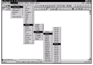
This hierarchical menu shows the contents of the Component library. The library was created and can be edited by the Component editor, although most users will not need to do much editing. One part of the menu looks like this:
Figure 2-18 The Component menu
The menu selects a component for adding to the schematic. The first level of the menu is divided into six sections.
Analog Primitives: The Analog Primitives section contains generic analog components for which the user supplies the values or model statements that define their electrical behavior.
Analog Library: The Analog Library section contains models for commercially available analog components. The values or model statements that define their electrical behavior are provided in the Model library.
Digital Primitives: The Digital Primitives section contains generic digital components for which the user supplies the values or model statements that define their electrical behavior.
51
Analog Library: The Digital Library section contains models for commercially available digital components. The values or model statements that define their electrical behavior are provided in the Model library.
Animation: The Animate section contains objects which change their display or respond to user clicks during a simulation. The objects include a seven-segment display, an LED, and a switch which toggles its state between 1 and 0 when you click on it. These objects are designed to operate in transient or DC analysis in conjunction with the Animate mode. In this mode, a single analysis step (time or DC voltage or DC current) is taken and the states and animate devices are updated on the schematic. MC6 then waits for either a key press or a specified time delay before taking the next time step. The purpose is to slow the simulation down to show individual node voltage or state changes.
Filters: This section holds filter macros created by the filter design function (accessed from the Design menu). It is absent until one or more filter macros are created.
Find Component: The last item in the Component menu is the Find Component command. Because there are over 12,000 parts in the Component library, you may need to search for a part without knowing its full name. This command lets you specify a part of the name. It then displays a list of the parts whose names partially match your name. You then click on the name of the part you want and MC6 sets the default part to the one you selected, a click away from adding it to the schematic.
If you enter a name for which there is an exact match, the part is selected for placement and no list is displayed.
You can use the standard wild card characters "?" and "*" in the search."?" stands for one unspecified character and "*" stands for one or more unspecified characters. An "*" is added to the end of your search string. For example:
52
(Blank) |
Finds all part names in the entire library. |
* |
Finds all part names in the entire library. |
LS3 |
Finds all part names that begin with LS3. |
D?22 |
Finds all part names that have D, then any single |
|
character, then 22, then any number of characters. |
To select a component for placement, use the cursor keys or click the mouse on one of the menu items. When you select a component, MC6 automatically changes the tool mode to Component.
To actually place the component, click the left mouse button in the schematic, or click and drag the component to where you want it to be placed. To rotate the component, click the right button before the left button is released.
The Windows menu
•Cascade: (SHIFT + F5) This command cascades the open circuit windows in an overlapping manner.
• Tile Vertical: (SHIFT + F4) This command vertically tiles the open circuit windows in a non-overlapping manner.
• Tile Horizontal: This command horizontally tiles the open circuit windows in a non-overlapping manner.
• Overlap: This command overlaps the circuit window and the analysis plotwindow. If the Plot on Top option is enabled, the circuit is maximized and a 1/4 size analysis plot is placed on top, otherwise the plot is maximized and a 1/4 size circuit is placed on top. This option is available only when a normal or Probe-mode transient, AC, or DC analysis is active.
• Maximize: This command maximizes a selected circuit window or circuit window icon.
• Arrange Icons: This command neatly arranges any minimized circuit window icons.
53
•Zoom In: (CTRL + numeric keypad + ) If the active circuit window is a schematic, this command magnifies the schematic. This command affects only the display, not the printed size. If the active circuit window is a text window, this command draws the window using the next largest font size.
•Zoom Out: (CTRL + numeric keypad - ) If the active circuit window is a schematic, this command shrinks it. The command affects only the display, not the printed size. If the active circuit window is a text window, this command redraws the window using the next smallest font size.
•Toggle Drawing/Text: (CTRL + G) Every schematic has a drawing area and a text area. The drawing area contains the schematic. The text area is a convenient place to store model statements, digital stimulus command statements, and source table statements. This command toggles the window display between the drawing and text areas.
•Split Horizontal: This command horizontally splits the front schematic window into its drawing and text areas for simultaneous viewing.
•Split Vertical: This command vertically splits the front schematic window into its drawing and text areas for simultaneous viewing.
•Remove Splits: This command removes any split panes in the
window.
•Component editor: This command accesses the Component editor. This editor is used to manage the Component library. Unless you are adding a new part to the library, or editing an existing one, you will not need to use this editor.
•Shape editor: This accesses the Shape editor. Each component in the Component library uses a graphical shape, which comes from the Shape library. This editor manages that library. Unless you are adding a new shape to the library, or editing an existing one, you will not need to use this editor.
54

•Package editor: This accesses the Package editor, which manages the information needed to generate netlists to drive popular PCB programs.
•Model Program: This command accesses the MODEL program, a stand-alone Windows program that models commercial parts by optimizing model parameters to fit data sheet specifications. It was used to model most of the parts in the library. Unless you are adding new parts to the Model library, you will not need to use this program.
• Calculator: This command accesses an expression-type calculator that can compute the numerical result of any MC6 expression. For example, while in transient analysis, you can type V(A) -V(B) to see the current differential voltage between nodes A and B, or PD(R1) to see the power currently being dissipated in resistor Rl. Variables are current values. If the simulation run is complete, these will be the ending values. If the run is currently paused, these are the values at the point of the pause.
• Files in Memory:
This group lists the open files in memory. If multiple circuits have been loaded, you can select any one of them for display from this list.
The Options menu
•Main Tool Bar: (CTRL + 0) This toggles the display of the main tool bar on and off.
•Status Bar: This option toggles the display of the Status bar on and off.
•Mode: This option accesses the Mode submenu. It contains these items:
 • Select: (CTRL + E) This mode selects objects for editing. To change attribute values like part name or model name, to edit a fragment of grid text, or to select a schematic region for moving
55
or deleting you must be in the Select mode. Normally, you invoke this mode by clicking on the Select button, or by typing CTRL + E, but you may also invoke it by selecting this menu item.
 • Component: (CTRL + D) This mode lets you add a component to the schematic. Invoke this mode by clicking on the Component button, typing CTRL + D, or selecting this menu item.
 • Text: (CTRL + T) This mode lets you add grid text to the schematic. Grid text can be used for node names and model statements (which can also be placed in the text area). Normally, you invoke this mode by clicking on the Text button, or by typing CTRL + T, but you may also invoke it by selecting this menu item.
 • Wire: (CTRL + W) This mode adds orthogonal wires to the schematic. Wires are used to connect components together. Normally, you invoke this mode by clicking on the Wire button, or by typing CTRL + W, but you may also invoke it by selecting this menu item.
 • WireD: This mode is used to draw diagonal wires in the schematic,
• Line, Rectangle, Diamond, Ellipse, Arc, Pie: These modes are used to draw graphic objects on the schematic or plot. You invoke these modes by clicking on the Graphics button in the Tool bar, then clicking in the window and selecting the desired graphic object from the menu that pops up.
 • Polygon: This command lets you place a polygon in an analysis
56
plot. The polygon is intended for use in defining valid specification ranges.
After rough drawing a polygon object, double-clicking on it lets you type in more exact values. The key words MIN and MAX place a polygon vertex coordinate flush with the plot sides.
 • Flag: This mode is used to place flags on the schematic. Flags are used to mark locations for quick navigation. Normally, you invoke this mode by clicking on the Flag button, but you may also use this menu item.
 • Picture: This mode lets you place picture files in the schematic.
 • Scale: (F7) This command puts the analysis plot in Scale mode.
 • Cursor: (F8) This command puts the analysis plot in Cursor mode.
 • Point Tag: This mode lets you place a point tag on a plot.
A point tag labels the X and Y values of a single data point on a waveform.
 • Horizontal Tag: This mode lets you place a horizontal tag between two data points. This tag measures and labels the horizontal difference between two data points on one or two waveforms, yielding pulse width or time delay if the X expression is Time.
 • Vertical Tag: This mode lets you place a vertical tag between two data points. This tag measures and labels the vertical difference between two data points on one or two waveforms.
 • Help: (CTRL + H) This command invokes the component help mode. This mode lets you click the mouse on a schematic component to see its parameter and model syntax.
 • Info: (CTRL +1) This invokes the Info mode. In this mode, 57
clicking on a component displays its model parameters, model statement, subcircuit description, or command statement, depending upon the component.
 • Point to End Paths: This command invokes the Point to End Paths mode. In this mode, clicking on a digital component displays all paths from the component clicked to all possible end points. End points include flip-flops and gates which drive no other gates.
 • Point to Point Paths: This command invokes the Point to Point Paths mode. In this mode, clicking on a digital component displays all paths from the first component clicked to the second component clicked.
•View: These options determine what will be drawn on the schematic.
 • Attribute Text: If checked, this shows component attribute text.
 • Grid Text: This option show grid text. Grid text is any text created with the Text tool.
 • Command Text: (ALT + .) Command text is any text created with the Text tool that begins with a period ("."). Command text is used to provide .MODEL statements and other specific commands to the simulator. This command lets you hide or display the command text.
 • Node Numbers: This option shows the node numbers assigned by the program to each node. Analog nodes have rounded rectangles and digital nodes have normal angular rectangles. Grid text placed on a node may serve as an alias for the node number.
 • Node Voltages / States: This option displays the last AC, DC,
58