

See discussions, stats, and author profiles for this publication at: https://www.researchgate.net/publication/282939817
Improved DC power distribution with multi-input single-control systems using boost converter
Article in International Journal of Applied Engineering Research · January 2015
CITATIONS |
READS |
3 |
38 |
5 authors, including:
Kuppusamy KarthiKumar
Veltech Multitech Dr. Rangarajan Dr.Sagunthala Engineering College
33 PUBLICATIONS 157 CITATIONS SEE PROFILE
Some of the authors of this publication are also working on these related projects:
Power quality monitoring View project
All content following this page was uploaded by Kuppusamy KarthiKumar on 06 January 2021.
The user has requested enhancement of the downloaded file.

International Journal of Applied Engineering Research
ISSN 0973-4562 Volume 10, Number 3 (2015) pp. 7815-7829 © Research India Publications
http://www.ripublication.com
Improved DC Power Distribution With Multi-Input Single-
Control Systems Using Boost Converter
1M.Karuppiah 2K.Karthikumar 3A.Arunbalaj 4L.Dhineshbabu 5S.Krishnakumar
Assistant Professors
Department of Electrical and Electronics Engineering Vel Tech (owned by RS trust) Engineering College Avadi, Chennai-62, Tamilnadu, India.
1karuppiah2730@gmail.com 2kumarkk1@gmail.com 3aarunbalaj@gmail.com
4dhineshbabu09@gmail.com 5krishna.veltech@gmail.com
Abstract
Environmentally friendly technologies such as photovoltaic’s and fuel cells are DC sources. In the current power infrastructure, this necessitates converting the power supplied by these devices into AC for transmission and distribution which adds losses and complexity. Now-a-days, due to power failure, there is a great used for UPS systems in our homes or in workplaces and also the amount of DC loads in our buildings is ever-increasing with computers, televisions, and other electronics entering our workplaces. This forces another conversion of the AC power to DC, adding further low power ratings, losses and complexity. Due to low power rating of the system, it is very important to reduce number of converter stages and use the generated energy efficiently. Therefore, instead of using different dedicated converters from various uni-directional renewable sources, this paper proposes a single stage boost converter with multiple inputs that can efficiently decimate generated energy. The proposed converter works under various operating modes which are discussed in this paper. This paper proposes the use of a DC distribution system.
Introduction
Increasing demand and environmental concerns have forced engineers to focus on designing power systems with both high efficiency and environmentally friendly. The natural resources such as fossil fuels while reducing the human impact on the environment through a reduction in pollution. The most well-known environmentally friendly is photovoltaic’s and wind turbines [1]. Although fuel cells are not considered an environmental friendly, but fuel cells have low emissions compared to other forms of energy. Unfortunately, the established power system infrastructures are
7816 |
M. Karuppiah |
based on alternating current (AC) while two of the leading environmentally friendly energies, fuel cells and photovoltaics, produce direct current (DC). Currently, power system infrastructures that wish to incorporate fuel cells and photovoltaics must first convert the DC power produced by these energy sources to AC [2]. This adds complexity and reduces efficiency of the power system due to the need of a power converter. Furthermore, a due to power failure, there is a great used for UPS systems in our homes or in workplaces and an increasing number of DC consuming devices such as computers, televisions, and monitors are being incorporated into our buildings. The power supplied to these devices must be converted again from AC back to DC adding further losses and complexity to the power system. Instead of using multiple converters to convert DC to AC and then AC to DC, the power system could only be based on DC. This would eliminate the need for two sets of converters for each DC load, reducing the cost, complexity, and possibly increasing the efficiency. However, a definitive analysis on a DC distribution system is needed to determine the net benefits of eliminating the converters. In the environmentally friendly energies photovoltaic, wind and fuel cells are having some of the drawbacks, likes night time, raining session and low wind there are low power generated in photovoltaic’s and wind, so reduces this drawback using multiple energy source for a distribution this paper, proposes the use of a DC distribution system using multi input single control system.
Problem Background
Since the development of electricity, AC has been describing as the better choice for power transmission and distribution. However, Thomas Edison one of the founders of electricity supported the use of DC. No method at that time existed for boosting and controlling DC voltage at the load, so that transmission of DC power from generation to load resulted in a large amount of losses and voltage variations at the different load locations. To resolve this issue, Westinghouse proposed AC distribution [2]. Tesla showed the practical advantages of alternating current. Transformers made it possible to step up an AC voltage easily, this allowed for efficient transmission of power from one location to another resulting in a complete transformation of the power systems to AC. Although many things have changed since the invention of electricity, AC is still the fundamental power type of our power infrastructure. However, due to the development of power electronics which gives a better utilization of existing transmission corridors with high voltage DC connections. High voltage DC transmission allows more power to be transmitted over a long distance with fewer losses compared to an AC transmission. Power electronics makes efficient and accurate control of electrical power possible. Efficient AC to DC, DC to AC and DC to DC conversion technology are now available on the market, where DC to DC conversion is more efficient than AC to DC conversion. Power converters and DC energy sources, interest in DC has returned. Several studies have investigated the use of a DC distribution system.
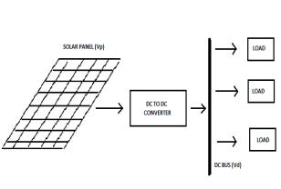
Fig. 1 shows the block diagram of a obtainable system. An input solar source (Vp) is interfaced to a DC distribution bus (Vd) using a DC to DC converter. It uses a DC
Improved DC Power Distribution With Multi-Input Single-Control Systems et.al. 7817
based distribution with various loads connected to it through dedicated point-of-load. The idea is basically inspired from computer power system. The renewable power sources are generally DC. Due to the intermittent nature of renewable sources, even though the generated power is AC or DC (e.g., solar power is DC and wind power is AC), they are converted to a DC and use it further processing. Another factor that improves efficiency is: more the distribution voltage (Vd) less is the current for the same power level. Therefore, a boost stage between the solar panel and distribution bus is advantageous [3]. The choice of voltage level is dependent on the power level of the distribution and available area for renewable installation. Never the less, in most implementations, a boost converter is used to interface the source with the DC bus. This is because, from MPPT point of view, in a smaller installation, the solar panels (generally, with open circuit voltage of 12-36V) are not preferred to be connected in series. They are paralleled as this arrangement has less impact on power generation. So reduce this power generation using conventional system of a single stage boost converter with multiple inputs that can efficiently decimate generated energy.
Figure 1: Existing system block diagram
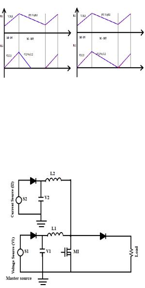
Proposed System
Future DC based system will have various sources interfaced to the DC-distribution bus as shown in Fig. 2. Unidirectional Renewable Sources are interfaced directly to the converter from which power is supplied to the distribution bus. When bidirectional sources are used it is directly interfaced to the distribution bus through a dedicated converter. Renewable Sources have varied characteristics, e.g., a solar array is a current source and a fuel cell is a voltage source. In order to interface all these sources to a single domestic supply grid, a converter has to be interfaced between the respective nodes. The converter takes care of the regulation and protection which arises because of the interfacing a multiport converter is described which uses multiple boost converters with common output as interfaces between various sources and the DC bus. A multi-input series output concept is used to realize this interface which works at ZVS. Most of the researches have addressed the multi-source power utilization problem by using individually controlled converters. That means, the

7818 |
M. Karuppiah |
source and DC bus have a dedicated converter between them. This option is quite good for higher power installations. However, in a DC bus where the power generation is limited and the sources have limited output, these options may not be the most efficient ones as more converters will degrade efficiency and reliability. This paper looks at an alternate circuit to realize a power electronic interface for DC bus, with multiple unidirectional input sources and a single output. The converter structure is realized using a single master control with multiple sources of relatively smaller power rating. The output of the converter is directly connected to a distribution network an additional stages as well as MPPT control.
The organization of paper is as follows Section II gives a problem background and existing system. Section III describes general topology of proposed Converter. Section IV and V describes the possible modes of operation a multi stage converter system with different input sources. Section VI describes the master source control. In Section VII experimental verification of proposed topology is done. Section VII presents conclusion of this paper.
Figure 2: The Proposed system block diagram
Multi-Input Single Control (MISC) Topology
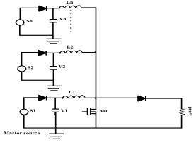
The overall topology is derived from boost Converter as shown in Fig. 3. There is a Master source S1 this source can be voltage or current source and slave sources S2 to Sn are interfaced to the drain of the control switch through dedicated inductors. The converter topology is referred to as Multi Input Single Control due to the fact that the master source is always in control of the duty [4]. The Master Source S1 fixes the duty cycle of switch Ml based on the MPP operating point of the input source, if input is a solar panel. In this case the current is used to supply the loads connected to this bus. In case of a voltage source, the output current of the boost can be controlled. The loads are connected to DC bus directly. As the converter topology is based on boost converter output voltage is always greater than input voltage for the operation of the converter.
Improved DC Power Distribution With Multi-Input Single-Control Systems et.al. 7819
Figure 3: Multi input boost converter
Depending upon the characteristics of the sources connected to the converter it can be classified either as a voltage or a current source.
It is important to note that all the common renewable sources are unidirectional in nature and should be interfaced with a diode. When a current source is interfaced to the converter, a capacitor is used at the input terminal as can be seen from Fig. 3. This capacitor is required to meet the ripple requirements of the converter input current. When the source has a voltage source property, an input capacitor is avoided as it will invariably force the capacitor voltage to become equal to the master source terminal voltage due to duty constraint.
Modes of Operation
The different modes of operation of MISC converter is as outlined in Table I. All the modes given in Fig. 4 are valid if the basic constraint of output voltage being greater than input voltage is satisfied. Note that the output of the converter is connected to DC bus. The resistive load represents the load on the DC bus. All the operating modes explained below are very much dependent on the design of input inductor. This design philosophy will be covered in the next section.
Table 1: Modes of Operation
|
Modes of Operation |
|
Mode |
Master Source |
Slave source |
I |
Current Source |
Voltage Source |
II |
Current Source |
Current Source |
III |
Voltage Source |
Voltage Source |
IV |
Voltage Source |
Current Source |
7820 |
M. Karuppiah |
Mode I: Current Source And Voltage Source
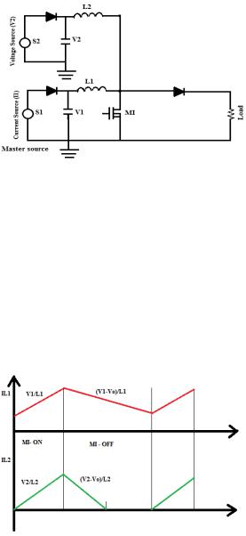
As shown in Fig. 4, when a current source is the master source and voltage source acts as a slave source there are two operating scenarios possible which is explained below as two sub-modes [2]. The duty ratio for these modes is fixed by the current source.
Figure 4: Current and voltage source inputs
1) Sub-Mode I-A: VI > V2:
When the input voltage of the master source is greater than that of the slave sources there will be 3 operating intervals for multi input boost converter, for a properly designed inductor, the current through the inductor (L1) of master source will be in current source. Therefore, for a similar or smaller value of inductor (L2), the current from slave source will be in voltage source. Assuming the L2 to be smaller is reasonable as the power rating of the slave source is not high. The inductor Current waveforms ILl and IL2 are as shown in Fig. 5.
Figure 5: Inductor current waveforms ILl and IL2
2) Sub-Mode I-B: VI ≤ V2:
When the master source terminal voltage is equal to that of the slave source, both the input currents are ideally in constant control mode. However, this may not be possible all the time, as the second source is assumed smaller. This may lead to the second
Improved DC Power Distribution With Multi-Input Single-Control Systems et.al. 7821
source working under current limit. Similarly, if slave source voltage is larger, for same duty cycle as the master, its current will invariably reach current limit. Therefore, all that can be said about this mode is that, in a practical development, the slave source works under current limit. The inductor current waveform IL2 indicated in Fig. 5 indicates the state of operation before the source current reaches its limit. When the slave source reaches current limit the inductor current waveform depend on the characteristics of source such as type of source, source impedance etc.
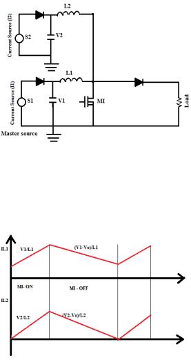
Mode 2: Current Source And Current Source
In this mode both inputs are current source is connected to multi input boost converter. It is shown in Fig. 6. The terminal voltages V1 and V2 will be forced to become equal by the duty ratio of the switch controlled by master source.
Figure 6: Current source inputs
For normal operation of MISC converter the inductor current waveforms are as shown in Fig. 7.
Figure 6: Inductor current waveforms ILl and IL2
7822 |
M. Karuppiah |
The normal operation of the converter is valid when input inductors and capacitors are selected properly. Ideally current IL I drawn from the source should be transferred only to the output and therefore this operating development is not efficient. To prevent this mode of operation the proper selection of Inductance and capacitance value is mandatory.
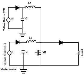
Mode 3: Voltage Source And Voltage Source
The inputs of MISC converter are connected to voltage sources as shown in Fig.7. In this mode of operation there are two sub-modes possible which are given below. The duty ratio for this mode is fixed by the master source.
Figure 7: Voltage source inputs
1) Sub-Mode III (A): VI > V2:
When input voltage of master source is greater than the slave source voltage there will be three operating intervals. The slave voltage source will be forced to operate in discontinuous current mode as the gain required is more [5]. As the power generated from the source is not very high, interfacing a separate converter for power extraction is not necessary and discontinuous current mode operation can be used for extraction of the available power. The input current waveform is as shown in Fig. 8.
2) Sub-Mode III (B): VI ≤ V2:
In this sub-mode of operation the input inductor currents I L I and I L2 ideally should operate in continuous current mode. As the duty ratio is fixed by master source, when input voltage of master source is less than or equal to the slave source voltage it will have a higher gain than required due to higher duty ratio. Output current from slave source increases till it reaches its current limit which is the equilibrium point of operation for the source [5]. The input inductor IL2 current waveform before the slave source reaches the current limit. When source reaches the current limit the operating waveform will depend of source characteristics such as source type, source impedance etc.
Improved DC Power Distribution With Multi-Input Single-Control Systems et.al. 7823
Figure 8: Inductor current waveforms IL1 and IL2
Mode 4: Voltage Source and Current Source
When a voltage source is the master source and a current source acts as a slave as shown in Fig. 9, the duty ratio of switch M1 is controlled by voltage source. The terminal voltage V2 of the current source will be forced to be equal to terminal voltage V1 and the current that can be supplied by the source is drawn from the source. There will be only two operating intervals.
Figure 9: Voltage and current source inputs
Under Normal operating conditions, when the input inductor and capacitors are selected properly, both the converters work in continuous current mode operation and the input inductor current waveforms are as shown in Fig. 10. Under high ripple operation which is caused when low value of inductance is selected and proper value of capacitance is not used to maintain the ripple the input current waveforms. This mode of operation is not preferred as the there is a negative portion of current which indicates the charging of the slave source input capacitor by master source which reduces the amount of current flowing to the output [6].