

7824 |
M. Karuppiah |
Figure 10: Inductor current waveforms IL1 andIL2
Master Source Control
As DC bus is a small residential supply system which uses DC voltage based power distribution to various domestic loads the major supply sources used will be renewable energy sources which are interfaced to MISC converter. The source with highest power rating will be designated as the master source and all other low power sources will be used as slave sources.
Figure 11: Characteristics of solar panel
When MISC converter is used to supply power in DC bus the master source is selected as a solar panel which is modeled as a current source. The characteristics of solar panel are as shown in Fig. 11 for a particular solar radiation level. The point represented by Maximum Power Point (MPP) is the ideal point of operation of the solar panel. With the variation in radiation level MPP shifts and hence a controller is necessary to track the shifting point. The tracking of MPP point is done by the varying the duty cycle of MISC converter. There are various methods of tracking MPP available in literature. The tracking of MPP is done with the help of Perturb & Observe (P&O) algorithm. The MPP point is calculated using P&O algorithm by

Improved DC Power Distribution With Multi-Input Single-Control Systems et.al. 7825
observing the change in power for the variation of duty cycle [7]. The direction of change of duty cycle is based on the direction of change in power. The slave sources that can be connected to MISC are as shown in Fig. 3. For Mode I operation a low power fuel cell can be interfaced as slave source. Depending on the terminal voltage sub modes I (A) or I(B) exists as the operating mode. For Mode II operation a lower power solar panel is interfaced as the slave source to the converter. If the panel is selected such than the MPP of slave source matches the MPP of master source in normal radiation level we can extract maximum power from both the panels with a single control switch. The input inductor and capacitor value is properly designed so as to prevent high ripple operation of the converter.
Experimental Results
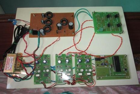
An experimental prototype and hardware is developed to test Mode I to Mode IV operation of MISC as shown in Fig. 12 and Fig. 13 respectively. The master source used is a solar panel. MPPT is implemented using a digital controller. A second voltage source or a full cell is used as the slave source depending on the mode of operation under test. The primary solar panel rated 34WNoc=2 1V and Isc=2.IA is used. perturb & observe algorithm is implemented on a PIC microcontroller during testing. The master source is a solar panel under MPP operation giving a terminal voltage VI = 14 V at MPP operating point and the dc source used has a terminal voltage of V2 =10 V. As explained in Section V under Mode I operation the current through slave source operates in discontinuous current mode. The discontinuous current mode operation of slave source provides the higher gain requirement, when two voltage sources are interfaced to MISC converter. The current IL1 passing through master source inductor.
Figure 12: The experimental prototype Model
7826 |
M. Karuppiah |
Figure 13: The experimental hardware Model
Mode II operation is observed as explained in Section V. The passive components used and the power ratings of the master and slave panels are as indicated in TABLE II.
Table 2: Components ratings
|
Components Specification |
|
|
Parameters |
Ratings |
|
L1 |
1.40mH |
MISC |
L2 |
600µH |
Converter |
Cin1 Cin2 |
850µF |
|
Co |
38µF |
|
Fswitching |
10kHZ |
Under Mode II operation If the inductor and capacitor values are properly selected it results is normal operation mode which is proved experimentally in Fig. 14 (a) and Fig. 14 (b). Both the inductor currents are in continuous current mode and maximum power is drawn from the master source which is under MPP operating point. The slave panel supplies the power that can be extracted at the particular point. If the inductor value used is very low which results in high ripple current, a high input capacitor has to be used to supply the required ripple. If the selection of capacitor value is not proper it results in high ripple mode of operation which is as seen in Fig. 15 (a) and Fig. 15 (b). The current IL2 passing through slave source has a negative portion which indicates the flow of current through inductor in opposite direction which is facilitated by the presence of input capacitor.

Improved DC Power Distribution With Multi-Input Single-Control Systems et.al. 7827
Figure 14(a): Master source under MPP operation.
Figure 14(b): Master source waveforms
Figure 15(a): Master source waveforms

7828 |
M. Karuppiah |
Figure 15(b): Slave current source waveforms
Conclusion
This paper proposed a Multi-Input-Single Control (MISC) converter. It accepts multiple inputs and boosts the voltage to distributing using a single control. A fixed duty cycle based on the highest power source (Master source) characteristics is used to control the circuit. The entire smaller sources act as slave and supply the power that can be extracted from it. Depending upon the interfaced source characteristics different modes of operations are possible. The modes operation is explained and the concept is experimentally validated using a prototype and hardware for different operating scenarios with a solar panel as a master source.
References
[1]D.Dong, I.Cvetkovic, D.Boroyevich, W.Zhang, R.Wang, P.Mattavelli, "Grid-Interface Bidirectional Converter for Residential DC Distribution Systems-Part One: High-Density Two-Stage Topology", IEEE Trans. Power Electron., Vol. : 28, no. 4, pp. 1655 - 1666, April 2013.
[2]Arun Sankar U, Soumya Shubhra Nag, Santanu K. Mishra “A Multi-Input Single-Control (MISC) Battery Charger for DC N anogrids978-1-4799- 0482-2/13/2013 IEEE.
[3]R.Adda, O.Ray, S.K.Mishra, A.Joshi, "Synchronous-Reference- FrameBased Control of Switched Boost Inverter for Standalone DC Nanogrid Applications ", IEEE Trans. Power Electron., vol. 28, no. 3, pp. 1219 - 1233, Mar. 2013.
[4]Yasir Arafat, Mohammad Amin, “Feasibility study of low voltage DC house and compatible home appliance design”.
[5]R.Adda, O.Ray, S.K.Mishra, A. Joshi, "Implementation and Control of Switched Boost Inverter for DC Nanogrid Applications," in Proc. IEEE
Improved DC Power Distribution With Multi-Input Single-Control Systems et.al. 7829
Energy Conversion Congress and Exposition (ECCE) 2012, Raleigh, NC, Sept. 2012. pp. 3811-3818.
[6]R.Adda, O.Ray, S.K.Mishra, A. Joshi, "DSP based PWM control of Switched Boost Inverter for DC Nanogrid applications," in Proc. 381h Annual Conference of Industrial Electronics Society (I ECON) 2012, Montreal, Canada, Oct. 2012, pp. 5285-5290.
[7]X.Li, A.Bhat, "Multi-Cell Operation of a High-Frequency Isolated DC/AC Converter for Grid-Connected Wind Generation Applications", Proc. of IEEE Int. Con! On Industrial and Information Systems (ICIIS), Dec. 2009, pp. 169 - 174.
[8]Gab-Su Seo, Jongbok Baek, Chul Woo Bak, Hyunsu Bae, Bohyung Cho, “Power Consumption Pattern Analysis of Home Appliances for DC-based Green Smart Home” Engineering Research Institute, Seoul National University Gwanangno 599, Kwanak-ku Seoul 151-744, KOREA.
[9]S.Poshtkouhi, O.Trescases, "Multi-input Single-inductor DC-DC Converter for MPPT in Parallel-Connected Photovoltaic Applications ", Proc. of 26th Annual IEEE Applied Power Electronics Conference and Exposition (APEC), Mar. 2011, pp. 41 - 47.
[10]C.Wang,M.H.Nehrir, S.R.Shaw,"Dynamic Models and Model Validation for PEM Fuel Cells Using Electrical Circuits", IEEE Trans.Energy Conver., vol. 20, no.2, pp. 442 -451, lun. 2005.
7830 |
M. Karuppiah |
View publication stats