

Ceramic Technology and Processing, King
.pdfCeramic Property Measurements 443
ceramic materials are now available and remain flat longer. On these, a diamond slurry of 9 to 30 μm diamond grit is used.
Loose abrasives can also be used for rough lapping when the ceramic is soft enough. A drip of water keeps the lap lubricated. Silicon carbide from 80-600 grit is a common abrasive for these ceramics. The lap wheel is cast iron with a spiral groove. These wear and require frequent re-machining. For this kind of installation, a sump is necessary to prevent clogging of the drains. Also, pitch the drain to the sump steeply or it will clog. Alumina powder is sometimes used for fine lapping in the range of 600-1200 grit. Remember to keep everything clean.
Polishing. Fabric-covered laps are used for polishing with diamondpolishing compounds in a lubricant liquid. Eight inch diameter laps are most common. Polishing machines are available and one type is shown in Figure 11.41.
Figure 11.41: Polishing Apparatus. A variety of polishing equipment is available. This is a common type. (Courtesy of Buehler)
444 Ceramic Technology and Processing
The machine can hold five or six samples. When there is an imbalance, a dummy section can be inserted in a blank opening. Newer machines do not require this. Fabric choice is important. Generally, a low nap fabric is used that can be nylon, a bonded-felted material, or cotton. Alumina polishes are best on nylon, while zirconia polishes are best on the bonded-felted material. Glasses polish on stiff foamed polyurethane with CeO2 polishing compounds. Plastics use alumina polishing compounds on higher nap cloths. This type of cloth is also useful for making a relief polish, which is where the softer materials are removed to a greater depth than the harder ones. This brings out the difference between the two phases, allowing their easy recognition. However, in general, a flat polish is sought with the features brought out by etching. Very flat surfaces can be produced on lead laps, but require expertise. The latter method is not common in the ceramics lab.
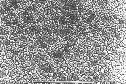
Polishing compounds are carefully-sized diamond powders that range from 30 to 1/4 μm. Polishing proceeds progressively from the coarsest to the most fine size. Clean thoroughly between abrasive sizes. An ultrasonic bath with a detergent or solvent is useful. Reflective surfaces develop with the 9 μm abrasive. When the surface is no longer reflective, change the procedure, usually with a different cloth. Final polishing is with 3 μm diamond for most purposes, but 1 and 1/2 μm abrasives are often used. If the difference is not discernable, then the extra steps are not especially worthwhile. During polishing, the rough-lapped surface is gradually removed. That surface contains scratches that have uneven scratch roots. These can be differentiated as they line up on the partially-polished surface, whereas porosity does not. Figure 11.42 is the polished surface of a dense alumina sample.
Much of what seems to be porosity is not. Rather, when the dark spots line up, they are scratch roots. Also, pores are often round where root pits are not. Scratch pits require additional polishing to remove them. However, it is often less work to go back and re-lap with a fine abrasive and then start to polish all over again. It depends on the depth of the pits.

Ceramic Property Measurements 445
Figure 11.42: Dense Fine Grained Alumina Ceramic. Polished section, plane light. When "pores" line up they are scratch roots, as shown by the arrows. Scale bar 200 μm.
Etching. Etching is often done to delineate microstructural features such as grain boundaries. Fine-grained, dense ceramics are usually thermally etched at about 1200-1300 °C for 15-30 minutes, presuming that the polished sample was first removed from the plastic mount. This is a preferred technique for alumina and zirconia. When the grain boundary phase or matrix is a glass, etching can be done with HF vapor by holding the sample with tongs above the acid. In other cases, the sample is immersed in the acid, which is diluted to produce the right amount of etching. A third way to etch a sample is to place it in a molten flux for a brief period of time. Alkali fluorides are common as fluxes, and the process can be done over a gas burner.
446 Ceramic Technology and Processing
The top surface of the polished section must be parallel to the top surface of the stage for the section to remain in focus. To accomplish this, place a thumbnail-sized piece of modeling clay on a glass slide and level it with a leveling press, which can be obtained from an accessories supplier.
Thin Sections. Thin sections are viewed with transmitted light, either plane or polarized. There are many techniques determining optical properties, but only a few are applicable to ceramics. These few include, when there is an advantage to viewing the material in depth through a cross-section, birefringence, microstructure, orientation, and details such as those on grain boundaries. A prerequisite is that the grain size is larger than the section thickness, in the range of 30-50 μm.
Making thin sections is difficult, especially for hard and tough ceramics. Residual stresses are the biggest concern for the following reasons. A section is made by slicing a thin piece of the ceramic, lapping one side flat, and cementing it to a glass slide. Epoxy adhesives are common. Next, the section is ground down on the opposite side to the required thickness and covered with a cover glass. Grinding or lapping result in residual stresses in the surface.2 Stress levels are affected by the coarseness of the abrasive; coarse abrasives impart greater residual stresses than fine abrasives. The side of the section against the slide was finish-lapped with a fine abrasive to give it a smooth finish. The other side is lapped initially with a coarse abrasive producing a difference in stress between the two surfaces. That the section tends to curve has been observed where the difference in calculated stress is as high as 30,000 psi. Spalling then occurs on the edges of the section, with the fragments tearing out additional material. If fortunate, the center of the section might be preserved.
High index of refraction ceramics such as zirconia must be polished on both surfaces because light scattering will cause foggy viewing.This situation is even worse, as the first polished surface is relatively stress-free while the other surface is being lapped with coarse abrasives and is in a state of high stress. Also, the first surface is smooth, with little surface area for the cement to grip. Spalling is severe under these conditions.

Ceramic Property Measurements 447
What can be done to reduce spalling? There are a few experimental solutions and some that are incomplete.
•Roughen the glass slide by lapping with 600 grit SiC.
•Use a stronger adhesive, hot melt?
•Lap the observation side of the sample with fine abrasives only.
•Use gentle and slow lapping, with a polishing apparatus.
Other problems with making thin sections include keeping the section flat, lapping a wedge, forming a dome, slicing finger tips on the slide edges, and grinding off finger tips. Keeping the section flat and parallel takes practice and concentration. There is a natural tendency to grind a dome as the slide rocks on the lap. It helps to grind preferentially on the center of the dome by placing a fingertip and pressing down directly on the high part.
With enough practice, the slide can be held flat. Standing at the lap is the preferred position, provided that the table is of a suitable height. The slide can be held in a special holder as shown in Figure 11.43.
Figure 11.43: Thin section Slide Holder.
448 Ceramic Technology and Processing
There is both a feel and observation when the slide is held flat. Body motion is much like a dance, where the wrists and arms are held stationary and the body rotates and shifts from the hips traversing the section across the lap surface. Periodically, turn the slide over and look to observe a wedge, with one end or side thicker than the other. The trailing edge of the slide laps faster than the leading edge because of the torque on the slide. Simply turn the slide around so that the thick part of the wedge is on the trailing edge. It also helps to press down harder on the thick side. Alternatively, the slide can be tipped up to hold it parallel to the lap surface. Then, look at it often and make further corrections.
As for cutting injury to the fingers, dull the slide edges slightly and use a slide holder such as the one shown in Figure 11.43. However, the best feel is when the slide is held directly with the fingers. Proceed with caution since the combination of vibration and cold water prevents pain in the fingers, often rendering an injury as a surprise. With practice and healing, thin sections will be made flat and of the right thickness. After much practice, the craft is mastered.
When using loose abrasives, the lap will wear unevenly, with the edge and center wearing less than the middle annulus. Because of the lap curvature, the lap will grind a dome on the section. Periodically, the lap must be machined flat. These laps have a spiral groove re-machined into the surface for distributing the coolant and abrasive, and breaking the suction.
Metal-bonded diamond laps dull and cease to cut. They can be rejuvenated by grinding a gritty ceramic such as an insulating fire brick against the surface. This wears away the bond and brings up additional diamond asperities. The procedure does, of course, wear the lap.
Care of the Optics. Microscopes have soft glass lenses that scratch easily and corrode in acidic gases. To avoid touching the objective lens to the sample, always lower the lens to where it is just above the sample surface and then raise it to focus. This becomes more difficult at high magnifications where this distance is small. When looking at granular materials on a slide, always use a cover glass and an index of refraction liquid. Using either a cover glass slide or a polished section ensures that the lens will not be damaged if it inadvertently touches the sample as it is in contact with a flat surface.
Ceramic Property Measurements 449
Keeping the lenses clean helps to obtain a sharp image. Clean properly to avoid scratching the lenses. Avoid rubbing an abrasive particle across the lens surface. Blow the lens off with a canned gas, or brush it lightly with a soft camels hair brush, then clean it with an organic solvent such as acetone and lens paper. Avoid vigorous rubbing. Facial oils are the main ocular contaminants.These oils pick up grit that can damage the lens if it is rubbed. Most of the oil is around the rim of the lens and can be cleaned using a Q-Tip moistened with acetone. Rubbing the bulk of the lens only spreads the oils out over the surface, so it is necessary to clean the edges first. Cleaning the edges first with a detergent works well on eye glasses. Objective lenses remain cleaner as they are out of the way. Cleaning is done by the same procedure, except when the dirt is abrasive, such as being splashed with a slip. Be very careful not to rub the lenses until all of the slip is blown or lightly brushed away.
Check List, Optical Microscopy
•Stereo-Binocular 40X max.
Oblique illumination Flexible illuminator Focus eye piece
•Universal
1000X max. Polished surfaces
Vertical illuminator adjustment
Measure: grain intercept, % phases, shape Oblique illumination, 100X max.
Thin sections Loose grain
Optical contrast Birefingence
Accessories: filar, rotating stage, mechanical stage Measure: grain intercept, percent phases, shape,
orientation, stresses
CLICK TO GO TO NEXT PAGE
450 Ceramic Technology and Processing
•Sample preparation Polished sections
Sawing
Impregnating: polymer, frit Ease edges
Mounting: casting, molding Lapping
Polishing: diamond abrasive, cloth, medium Etching: thermal, acid, flux
•Thin sections
Residual stresses Plucking problems Flatness
Loose lapping abrasives, cast iron laps
• Care of the optics Grit removal Solvents Cover glass
Electron Microscopy
Described below are Scanning Electron Microscopes (SEM) and Transmission Electron Microscopes (TEM). Both microscope types can be equipped with chemical analytical capability. There are two types of analytical capability, energy dispersive (EDX) and wave length dispersive (WDX). Both are ways of analyzing the X-ray fluorescent spectra emitted from a spot on the sample surface energized by the electron beam.
Electron microscopes use an electron beam rather than visible light to probe the sample. An electron beam is more energetic and capable of resolving to much higher magnifications. The beam is focused with electromagnetic lenses to produce an image on a monitor or photographic film.

Ceramic Property Measurements 451
Scanning Electron Microscopes (SEM)
Scanning electron microscopes scan across the sample surface with an electron beam. They are useful over a wide range of magnifications from a few diameters up to about 20,000X. An instrument is shown in Figure 11.44.
Figure 11.44: SEM Instrument. There are several good manufactures of SEM equipment. (Courtesy Amray, Ferro)
452 Ceramic Technology and Processing
Modern instruments, more user-friendly than those of 10 years ago, continue to improve. Software is extensive and versatile. While capable of higher magnifications, surface charging occurs and blurs the image since most ceramics are electrically insulating. Scanning the sample surface results in a great depth of field. This capability is very useful as the entire vertical dimension of the sample surface is in focus, as will be seen in the subsequent discussion. A very common application of the SEM is to observe microstructure when the grain size is too small for an optical microscopes. Figure 11.45 is the thermally-etched, polished surface of a TZP sample.
Figure 11.45: Yttria stabilized Zirconia(TZP) Fine-Grained, Dense Ceramic. Thermal etch. SEM Photograph. Scale bar 10 μm.
The ceramic is fully dense with an average grain intercept of less than 1 μm; evidence that it was well-crafted.