

Figure 19
 f)
Stabilizers
f)
Stabilizers
These are run between the drill collars and are of a blade type construction. Drilling fluid can pass freely between the blades while the outer edge of the blades contacts the wall of the hole and holds the drill collars firmly centered in the hole. They do exactly as their name implies, they provide stability to the bit and collars. This is important as it improves bit life, in addition to keeping the direction of the hole under control. (Figure 20)
g) Reamers
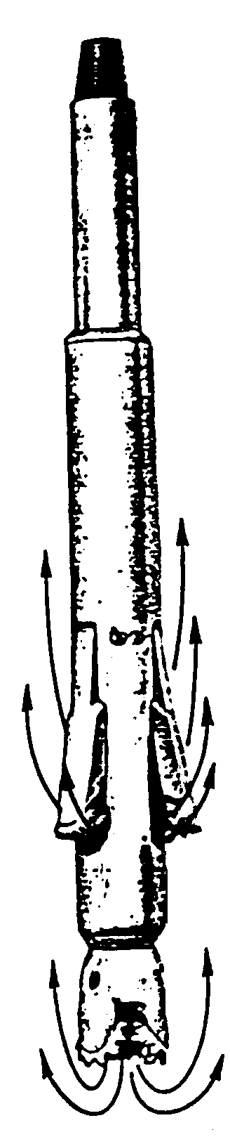
Figure 20
These usually have the same diameter as the bit and are run a little distance above it.. As the bit wears out it tends to decrease in diameter and consequently start drilling a smaller hole. The reamers’ function is to cut the hole out to full size behind the bit.
h) Under-reamers
Figure 21
Used for drilling or opening out a hole below a restriction such as imposed by the blow-out preventer assembly. They are run above a conventional roller bit having their cones on collapsible arms, enabling it to pass through a narrow opening. When required, the arms can be opened, usually by the drilling fluid pressure, and a larger hole is thus drilled. (Figure21)
I) Hole Openers
These are run above a conventional roller bit and are used for drilling large diameter holes. They have replaceable cutters and serve the same function as an underreamer except they are not collapsible and can only be used when there is no restriction smaller than the hole size they drill. (Figure 22)
j) Jars
Jars are fitted into the drill string and are used in the event of the drill string becoming stuck. They provide upward or downward jarring blows that help freeing the string. Jars use different mechanisms including hydraulic and mechanical.
k) Monel
Figure 22
This is a non-magnetic drill collar used to contain the magnetic survey tools, the monel is made of special non magnetic alloy that does not affect the reading of the survey tools that determine the hole deviation depending on the deflection from the magnetic deflection of the earth sphere.
l) Subs
A sub refers to any short Length of pipe, collar or casing that is made to perform a specific job. The most common types of subs you can find on rigsite are the following:
a. Crossover Sub:
A crossover sub is designed with different threaded ends for changes between different sizes and types of drill pipe or collars.
b. Bit Sub:
This sub is used to save the thread of the bit from excessive break out such as to change nozzles or BHA, So the break out of the bit is usually done at the connection between the sub and the upper collar pipe. The sub is ended with a box on both ends so that pipe and collars are always run pin down.
c. Shock sub:
This is run behind the bit with a steel spring or rubber packing to absorb the impact of the bit bouncing on hard formations and prevent damaging the rest of the drill string.
d. Bumper Sub:
This is a free telescopic sub with 6-8 ft closure. Its purpose is to absorb the effects of heave on a floating rig. and not transfer it to the bit, these are now largely replaced by the "motion compensator" which is a hydraulic device attached to the travelling block so that the entire drill string remains stationary as the rig heaves.
e. Bent sub:
This is a non-straight sub designated with different bending angles, it is fitted in the deviating bottom hole assembly above the mud motor to drill deviated holes. The angle of bending is selected according to the inclination building rate and the length of the interval to be drilled with this sub.
f. Float valve:
This is a small mechanical one way valve inserted inside the bit sub, the valve allows mud to flow in one direction from the string to the annulus, This valve is usually used while drilling the surface hole sections, the penetration rate is usually fast causing the annulus becomes loaded with cuttings, a differential pressure takes place between the annulus and the string, once pumps are shut-off, the valve is mechanically closed preventing any back flow to occur .