

Riser and Guideline Tensioners
The marine riser is essentially a conduit, but its a main purpose is to maintain contact with and give access to the borehole when drilling. (Figure 18)
Riser tensioners provide tension to the marine riser pipe below the telescopic joint by a system of wires joined via sheaves to a series of pneumatic cylinders.
Its purpose is to maintain the riser in tension at all times regardless of the heaving of the rig.
It is common practice to install four or six tensioners, each with a load rating of around 60,000 lb.
Compensation for vertical movement several times the length of the stroke of the pistons is possible, due to multiple cable turns around the pistons.
Guideline tensioners operate on the same principle as the riser tensioners.
Their purpose is to maintain the correct tension in the guidelines between the rig and the guide base (which sits on the seafloor), regardless of the heaving of the rig.
The guideline tensioner is designed to deal with tensions of less than 10,000 lb; therefor, wires, cylinders and other components are smaller than those used in the riser tensioner system.

Figure 18
21. Drill String
This term includes all the components used to drill below the kelly or top drive; and it can include the following components:-
a) Drill Pipe & Tool Joints
The drill pipe furnishes the necessary length for the drill string and serves as a conduit for the drilling fluid. The drill pipe lengths (joints ) are hollow seamless tubes where the tool joints ( connections ) are separate components and are attached to the pipe at both ends to complete the manufacture of one joint. Tool joints are of thicker outer diameter to withstand the torque applied by tongs to tighten the connection. The drill pipe joints are normally made in approximately 30 ft/9.5m lengths.
b) Heavy weight drill pipe (HWDP)
This is the same as a drill pipe but with a smaller inner diameter and longer tool joints. Because of its wall thickness, its pound-per-foot weight is greater than an ordinary drill pipe.
Heavy weight drill pipe is inserted as a section between the drill pipe section up and the lower drill collars section to serve as a transition section between the two of them, this gives the drill string the required elasticity.
c) Thread Protectors
These are either made of metal or plastic and fit on both ends of a threaded pipe (box and pin ends) to protect the threads from corrosion and mechanical damage during storage or transportation. Obviously, they must be removed before use.
d) Drill Collars
Th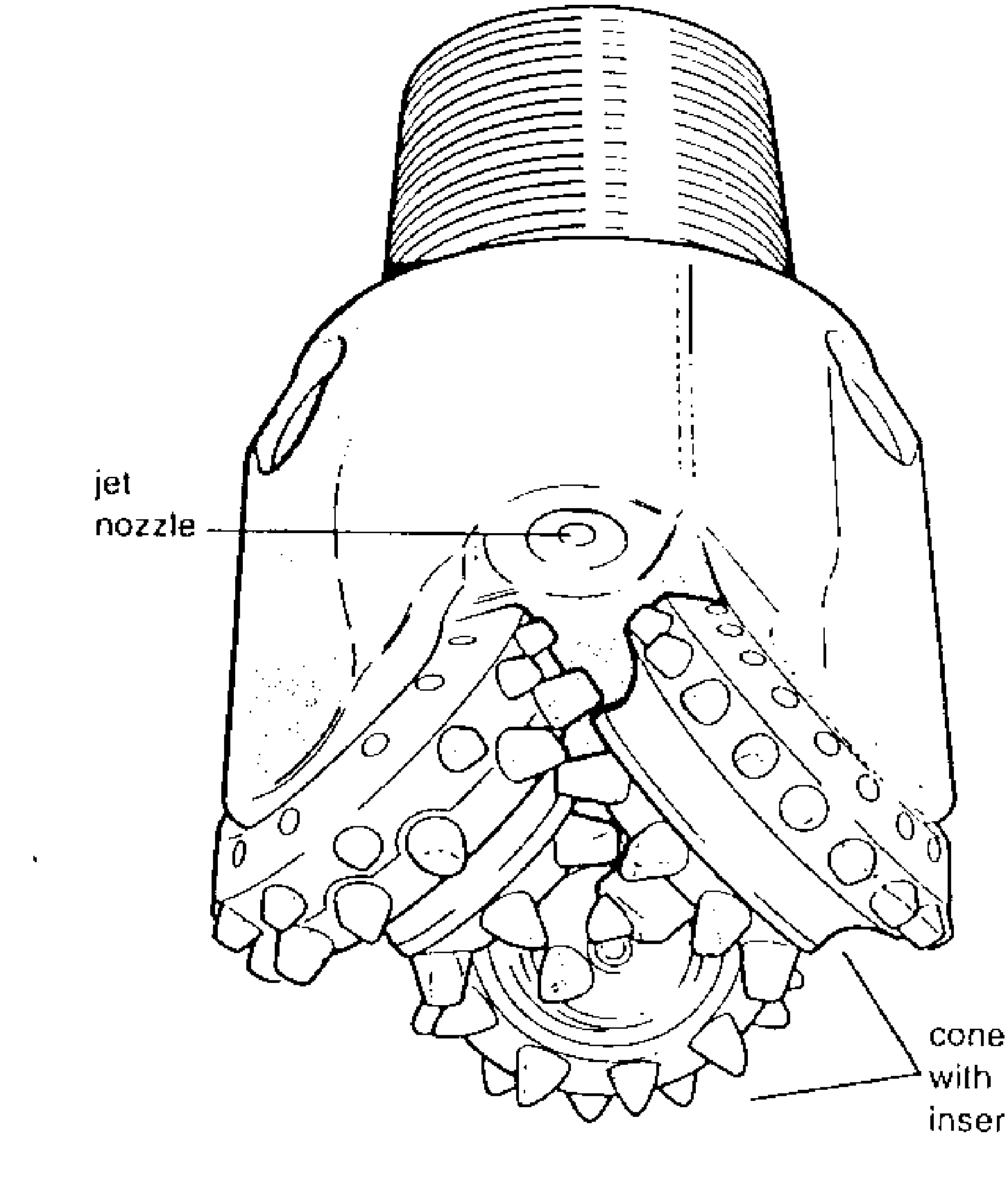 ese
are heavy walled, spiral and large outer diameter steel tubes. Their
function is to supply the desired weight on bit and to allow the
lighter drill pipe to remain in tension. The spiral grooves are to
minimize the surface of contact between hole and pipe reducing the
risk of getting stuck. This also helps the drilling fluid to flow up
the annulus in case of tight hole.
ese
are heavy walled, spiral and large outer diameter steel tubes. Their
function is to supply the desired weight on bit and to allow the
lighter drill pipe to remain in tension. The spiral grooves are to
minimize the surface of contact between hole and pipe reducing the
risk of getting stuck. This also helps the drilling fluid to flow up
the annulus in case of tight hole.
e) Rotary Bits
These may be classified into three general types :
1. Drag Bits:- these have no moving parts but drill by the shovelling action of their blade on the formation.
2. Roller Bits:- first designed by Howard R. Hughes in 1909. These may have originated from one to numerous individual rotating cones.
Three cone bits (Tri-Cone) are the most widely used in the oil field. The length and spacing of the teeth depend on the type of formation that the bit is designed to drill.
Ha rd
formation bits may have tungsten carbide “inserts” instead of
teeth. Various types of bearings are in use. Specially designed jet
nozzles are set on the bit to direct the drilling fluid to produce a
high velocity fluid stress on the bottom of the hole. So called
conventional bits were forerunners of roller bits but were
open-ended; i.e. without jets.
rd
formation bits may have tungsten carbide “inserts” instead of
teeth. Various types of bearings are in use. Specially designed jet
nozzles are set on the bit to direct the drilling fluid to produce a
high velocity fluid stress on the bottom of the hole. So called
conventional bits were forerunners of roller bits but were
open-ended; i.e. without jets.
3. Diamond Bits:- These are designed to drill by the scraping action of diamonds set in a steel matrix. This type of bits is normally used in hard formations where long bit life and the subsequent reduction in trip time are desirable. (Fig 19)