

Figure 14
Figure 15

16. Kelly
This is the topmost joint in the drill string and is 40-45 feet in length. It is commonly square or hexagonal. The kelly passes through the rotary table and transmits the table rotation to the drill string via the kelly bushing. (Figure 15)
17. Kelly Bushing
This engages with master bushing either by having a square lower section or by four pins fitted into holes around the central opening. This transmits the rotations to the kelly. (Figure 15)
18. Master Bushings
Through the master bushings, the rotary table transmits rotary motion to the kelly drive bushings and the kelly. They are also the connecting link between the rotary table and the slips which support the pipe during trips.
18. Swivel
Figure 16

The swivel supports the drill string and allows rotation at the same time. It also allows the passage of drilling fluid from the rotary hose into the drill string. The swivel performs a very tough job supporting a load that can be measured in hundreds of tons. This string could also be rotating at 200 or more revolutions per minute. Abrasive drilling fluids are often pumped through it at the rate of perhaps a thousand gallons a minute at a pressures that can exceed 3,000 psi.
The swivel is hung from the hook by the swivel bail and is connected to the rotary hose by the goose neck. Inside the housing just below the goose neck is the wash pipe. This is made of the strongest material known to the industry. The wash pipe is stationary and is joined to the rotating swivel stem. Special packing to seal this rotating joint is contained in the stuffing box. The bearings run in an oil bath. (Figure 16)
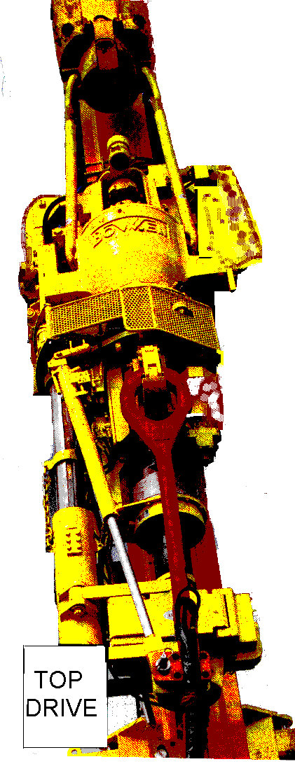
19. Top drive
This is a specially designed electric or hydraulic motor installed on the drill lines that replaced kelly and kelly bushing and it rotates the string as well.
Using the top drive enables drilling to be carried out stand by stand instead of joint by joint. This reduces the number of connections to be made while drilling. (Figure 17)
Unlike the kelly, Top drive is not removed during trips.
20. Heave (Motion) Compensation
Heave Compansators are used on semisbus and float ships rigs. The two basic types of motion compensators are:
Drill string compensator
Riser and guideline tensioner.
Drill string Compensator:
The drill string motion Compensator system is designed to nullify the effects of rig heave on the drill string or other hook-supported equipment. (Figure 18)
Mounted between the hook and travelling block, the compensator is connected to deck mounted air pressure vessels via a hose loop and standpipe and is controlled and monitored from the driller’s control console.
While drilling, the drill string compensator controls the weight on the bit. The driller lowers the travelling block to account for drill-off and to maintain the compensator cylinder within its stroke capacity while the drill string compensator automatically maintains the selected bit weight.
As the rig heaves upward, the compensator cylinders are retracted and the hook moves downward to maintain the selected loads.
Actually, the hook remains fixed relative to the seabed; the rig and compensator move, producing relative motion between the hook and rig.
The motion of both the kelly and drill string is relative to the rotary table.