11. Prime Movers (Engines )
The majority of the rig power is consumed by two operations :
A. Circulation of the drilling fluid.
B. Hoisting and/or Rotating.
These two operations couls occur at the same time. The power consumption of the circulation system is essentially constant, where in the hoisting the prime movers must be capable of handling highly variable loads at rapid acceleration over a wide range of speed and torque.
TYPES OF PRIME MOVERS :
A) Steam Engines:
These were the first engines used but have mainly been replaced by the following two types.
B) Electric Motors
Both AC and DC motors are in use. DC type is most widely used today because it has a wide torque and speed range and is easily controlled. DC-powered rigs fall into two categories: one uses DC generators and the other, which is gaining popularity, uses AC generators along with Silicon Controlled Rectification (SCR) to produce the required DC power.
C) Internal Combustion Engine
This is the most commonly used engine type due, in part, to the availability of diesel fuel. These engines are in fact inferior to both steam and electric motors. Their torque speed characteristics may be improved by the use of torque converters, but with a loss in efficiency.
12. Transmission
On a multi-engine rig the series of chains and clutches that connect the engines to the drilling equipment is called the transmission.
13. Draw Works
It is the control centre from which the driller operates the rig. It contains the clutches, chains, sprockets, engine throttles and other controls that enable the rig power to be diverted to the part of the operations at hand. It also houses the drum that spools the drilling line during hoisting operations and allows feed-off during drilling. A brake is used by the driller to control the speed of the drum while operations. Draw Works are commonly designated by horse power and depth rating. (Figures 12&13)

Draw works
Figure 12
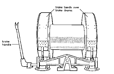
Brake
Figure 13
14. Drilling Line
This line affords a means of handling the loads suspended from the hook during all drilling operations. The wire line most commonly used is the 6 19, Seal construction, fibre core, plow steel cable. Where dictated by high load requirements, premium grade lines with an independent wire rope centre are used.
The drilling line runs from the main drum up to the crown blocks and down to the travelling blocks. The line is slung several times around the blocks. From the crown blocks the line goes down to the drill floor where it is attached to the anchor. This section of the line is known as the “dead line” since it is stationary. (Figure 09)
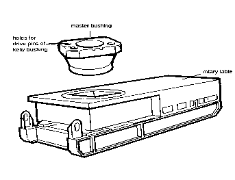
15. Rotary Table
This performs two functions:
1. It transmits the rotation to the drill string by turning the kelly joint.
2. It suspends the drill string weight during connections and trips.
Rotary table is usually driven by a chain from the drawworks on mechanical rigs and by its own motor on electrically driven rigs. Some are capable of speed of up to 400 RPM.
A rotary table is defined by the size of its central opening; the largest being 37½ inches. This opening is fitted with a master bushing which is split into two parts. (Figure 14)