

10.Mud temperature sensors
Tw o
types of temperature sensor are in use. Either semiconductor
thermistor transducers or platinum resistance elements (PRT) are
used. These are mourned in a protective cage at the end of all sensor
poles.The Temperature-In
sensor is mounted in the suction pit and the Temperature-Out
sensor
in the shaker header box.
o
types of temperature sensor are in use. Either semiconductor
thermistor transducers or platinum resistance elements (PRT) are
used. These are mourned in a protective cage at the end of all sensor
poles.The Temperature-In
sensor is mounted in the suction pit and the Temperature-Out
sensor
in the shaker header box.
The thermistor sensor is supplied with an 8.5 volt excitation voltage. The current output of the sensor is dependent on temperature and varies linearly between 270 and 370 microamps. This signal is converted by the signal conditioner card into a 0-10 VDC analog signal for input into the computer.
The Platinum Resistance element has a 4-20 m.a. converter in the sensor head and uses a 24 VDC excitation voltage from the signal conditioner.
11 .Mud density sensor
The Mud density sensor is of the differential pressure type. Two silicon oil filled diaphragms are placed one foot apart in the drilling mud and a highly accurate differential pressure transducer interrogates the readings and transmits a 4-20 m.a. signal to the computer.
The sensors are mounted in the suction pit and in the shaker header box to provide the density In&Out measurements.
The span can be adjusted over the desired range through calibration at the sensor head.
The sensor is supplied with 24 VDC excitation supply and produces a 4-20 m.a. signal. This enters a signal conditioner card and is fed to the computer as a 0-10 VDC signal.
For long term rig installations we recommend the resonant density sensors. Their superior accuracy and reliability give an on-line density reading that can be used with confidence by the customer and rig operator.
These sensors can be mounted in the mud pump suction lines. This allows the sensors to pick up the density of the fluid being pumped. The sensors rapidly detect the presence of the wrong fluid being pumped and can save rig time and money by early detection of miss-aligned pits. Unlike differential pressure sensors they are unaffected by turbulence in the pits and they maintain accurate calibration over long periods.
12. Mud conductivity sensor
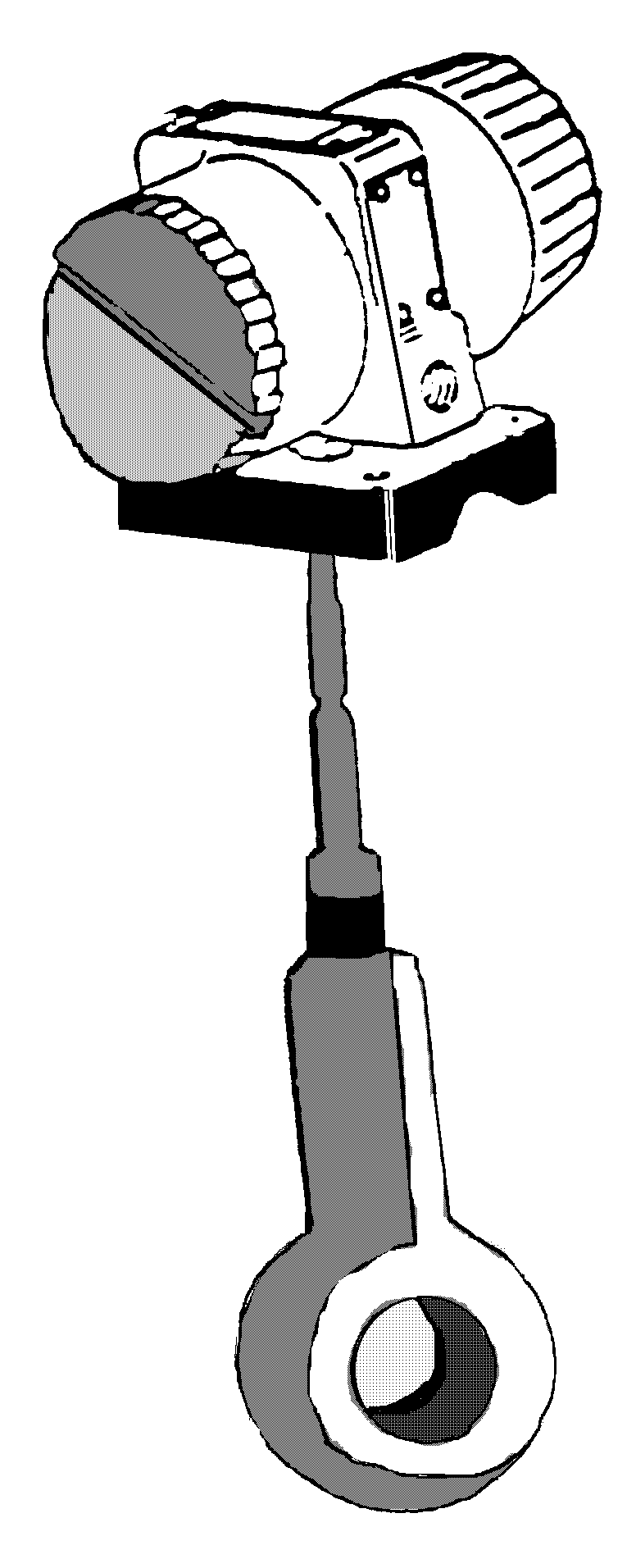 The
sensor is a new 4-20 m.a. type which has all the electronics in the
sensor head and gives a 4-20 m.a. signal to the unit. This signal is
then put through a density (or new conductivity) signal conditioner
card (both are exactly the same) to produce a 0-10 VDC signal for the
computer.
The
sensor is a new 4-20 m.a. type which has all the electronics in the
sensor head and gives a 4-20 m.a. signal to the unit. This signal is
then put through a density (or new conductivity) signal conditioner
card (both are exactly the same) to produce a 0-10 VDC signal for the
computer.
Principle of operation:
The sensor works on the principle of the toroidal coupling effect. The sensor contains two coils, known as the primary and secondary coils. AC current is fed to the primary coil by a Oscillator. The magnetic effect caused by this current is transmitted to the secondary coil by the medium surrounding the coils. This produces a current in the secondary coil, whose phase difference is related to the resistivity of the medium. The phase difference by a demodulation unit and then amplified to a 4-20 m.a. signal. The sensor also contains a thermistor for temperature compensation, so that the actual value given is at it’s 20° equivalent.
The 4-20 m.a. signal from the sensor is conditioned through a density/conductivity signal conditioner and then fed to the computer as a 0-10 VDC.