

7.Analog rotary speed sensor
The unit consists of a small low-power D.C. generator. This generator is driven via a belt and pulley from the rotary table drive shaft.
The unit produces 7 VDC per 1000 Revolution Per Minute (RPM).
The Final RPM will depend upon the gearing. The DC signal is isolated through a signal conditioner electronic board .
8.Pit volume sensors
 The
pit monitoring system uses a Delaval
sensor to monitor individual pits. The computer system allows a total
flexibility in defining the active and reserve pit systems. The
configuration can be changed quickly through the keyboard. Alarms are
computer controlled and can be set up for low and high levels on the
active system, the reserve system, or on individual pits. The system
can monitor up to 16 pits.
The
pit monitoring system uses a Delaval
sensor to monitor individual pits. The computer system allows a total
flexibility in defining the active and reserve pit systems. The
configuration can be changed quickly through the keyboard. Alarms are
computer controlled and can be set up for low and high levels on the
active system, the reserve system, or on individual pits. The system
can monitor up to 16 pits.
On trips the gain tank and trip tanks are also assigned through the trip monitoring programme for complete coverage of the pit system.
On connections the expected flow back gain encountered at various pump rates is entered. The system can correct for alarm if unexpected changes are seen during the connection.
Delaval sensor use a non contacting magnetic float activate discrete reed switches in reed switch resistance string inside a stainless steel pole. The position of the float determines the resistance and hence the voltage fed to the computer.
The system is very robust and has been field proven for years as the simplest and most reliable of pit measurement in standard situations.
If access is severely restricted or the pits are deep, we use ultrasonic sensor. The Endures and Hawser DU 523 Z is normally specified. These have microprocessor based filtering in the sensor to condition the signal and reject spurious echoes, temperature compensation self monitoring for faults and a simple calibration procedure.
Ultrasonic
9.Flow out sensors
Flow Padle Type
Th e
flow out sensor normally specified is of the paddle type. Flow in the
flowline causes a rotation of the paddle and a corresponding rotation
of a 1 turn potentiometer. Various paddle sizes are available to suit
the different flowlines. Non-linear and logarithmic calibrations in
the computer allow accurate calibrations to be made for most
installations over a wide range of flows.
e
flow out sensor normally specified is of the paddle type. Flow in the
flowline causes a rotation of the paddle and a corresponding rotation
of a 1 turn potentiometer. Various paddle sizes are available to suit
the different flowlines. Non-linear and logarithmic calibrations in
the computer allow accurate calibrations to be made for most
installations over a wide range of flows.
Th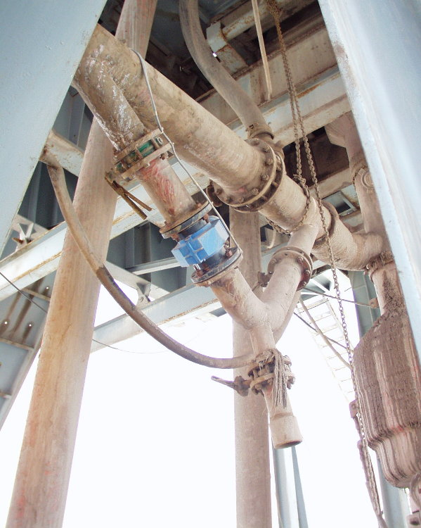 e
sensor is supplied with a 10 VDC excitation supply which is fed
through the 10 KOhm, one turn high accuracy potentiometer. This gives
a signal output of 1-10 VDC. This analogue signal is input directly
to the computer. If a pressure rated flow sensor is required for
installation on offshore diverted systems, a Martin-Decker MFTX05A
non-contacting mud flow sensor can be supplied on request. The paddle
flow sensor is a well proven and rugged instrument. However the
accuracy of its measurement depends on the installation in the
flowline. As the flow in the flowline is such an important
measurement for the well and rig safety we recommend the installation
of a magnetic flowmeters for long term contracts and where the rig’s
construction allows. The magnetic flowmeter has to be mounted in a
section of the flowline which is full to provide an accurate
measurement. The most recent designs of meter will work in fluids
with a conductivity above 1 micro mho/cm. In practice this will allow
use in most field oil base muds.
e
sensor is supplied with a 10 VDC excitation supply which is fed
through the 10 KOhm, one turn high accuracy potentiometer. This gives
a signal output of 1-10 VDC. This analogue signal is input directly
to the computer. If a pressure rated flow sensor is required for
installation on offshore diverted systems, a Martin-Decker MFTX05A
non-contacting mud flow sensor can be supplied on request. The paddle
flow sensor is a well proven and rugged instrument. However the
accuracy of its measurement depends on the installation in the
flowline. As the flow in the flowline is such an important
measurement for the well and rig safety we recommend the installation
of a magnetic flowmeters for long term contracts and where the rig’s
construction allows. The magnetic flowmeter has to be mounted in a
section of the flowline which is full to provide an accurate
measurement. The most recent designs of meter will work in fluids
with a conductivity above 1 micro mho/cm. In practice this will allow
use in most field oil base muds.
Electromagnetic Wave Type (EWS System)
The sensor is installed in a closed V-shaped piping and measure the flow through generating induction voltage in a magnetic field.
The v- shaped piping is designed to keep the inside of the sensor always filled with fluid.