

Figure 07
b) Derricks
There is no clear-cut distinction between a mast and a derrick. Often, the two terms are used interchangeably.
To keep things simple we will regard a derrick as the framework-tower type of support usually associated with oil well drilling. Typically derricks are assembled on-site bolting individual pieces together. The rigging-up time for this method is of course, longer than for a cantilever mast. (Figure 07)
2. Substructure
This is the support on which the derrick rests. It also acts as a support for the heavy equipment on the rig floor. The top of the substructure varies in height from 10-30 feet above the ground. This clearance is provided so that wellhead equipment can be installed underneath the rig floor. (Figure 08)
3. V-Door
This is a triangular opening on the front of the derrick to allow drill pipe and equipment to be picked up from the catwalk and brought into the derrick.
4. Monkey Board
This is a platform situated at a specific height from the rig floor, typically 60 to 90 feet, on which the derrickman works during trips. This platform also supports the fingers that are used to rack the stands of drill pipe .
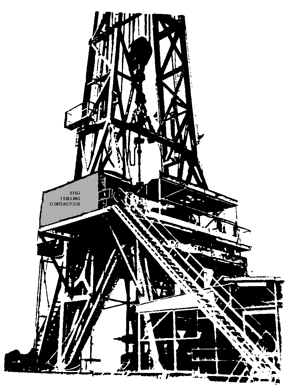
Figure 08
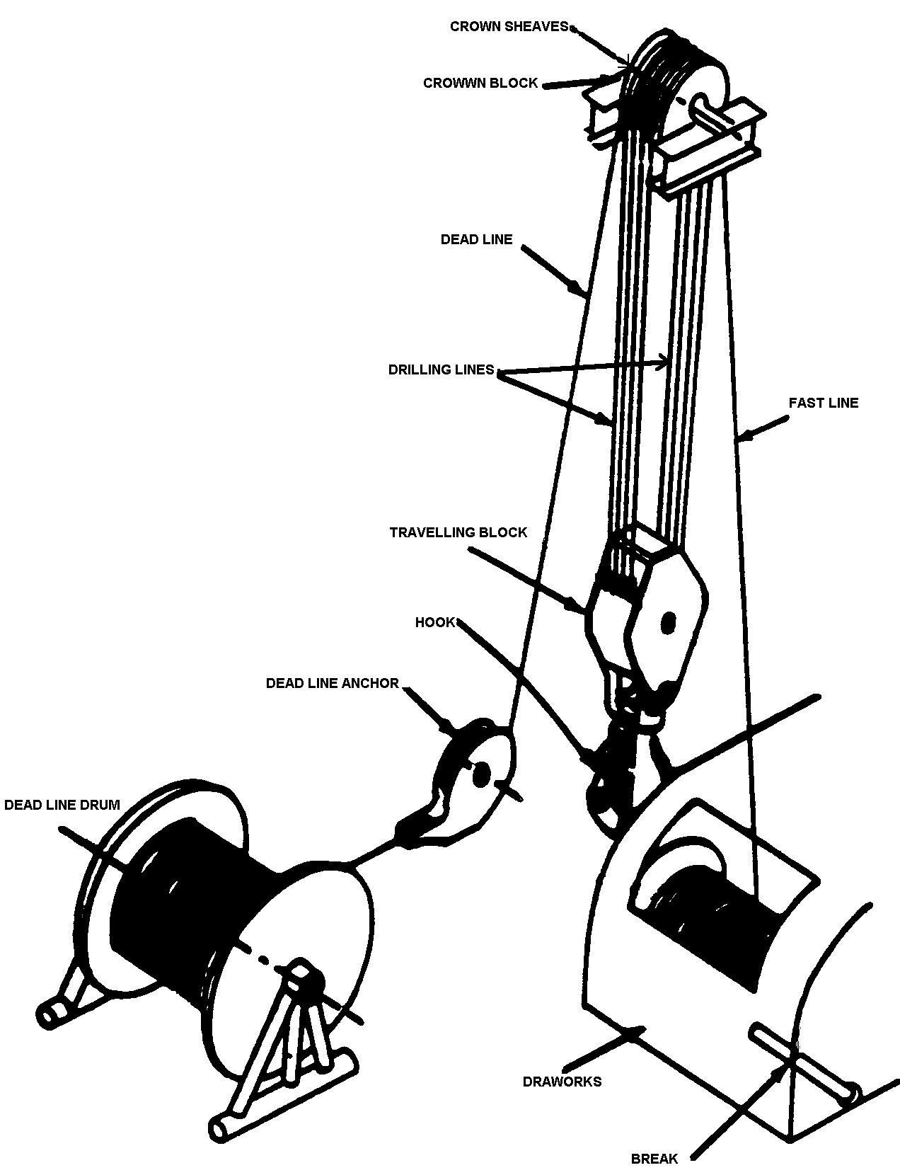
5. Crown and Crown Blocks
The top of the derrick is known as the crown, it is usually a small platform designed to carry the crown blocks. The crown blocks are the uppermost set of sheaves on which the drilling line is strung, most crowns of recent manufacture have from four to six sheaves. (Figure 09)
6. Travelling Block
This is merely the travelling pulley (sheave) assembly that is slung from the crown blocks by the drilling line. It connects the drilling line to the hook and swivel. (Figure 09)
7. Hook
This is suspended directly from the block. It is composed of a main hook which carries the swivel bail and two smaller offset hooks carrying the elevator arm bails. The hook can rotate in the axis of the travelling block, limited by a lock device ; it is also sprung. (Figure 09)
8. Elevators
Two elevators are hung from the hook on the elevator bails and are used for latching around the drill pipe in order to lift it. Elevators are of many slightly differing designs and sizes for use with different pipe sizes, drill collar and casing sizes. They are not used during the drilling operation but are necessary for lifting the pipe during a trip. Figure 10)
9. Slips
Th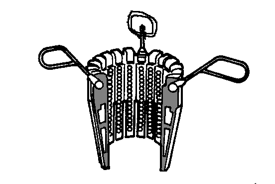 ese
devices are used to hold the weight of the drill string when it is
not supported by the hook (during connections or tripping time).
Slips are made of hinged sections with a single opening. They are
placed around the pipe, their tapered outer sections fitting against
either the inside surface (bowl) or the master bushing or against the
inserts. As the pipe is lowered, the slips tapered section causes
them to close tightly around the pipe. (Figure
11)
ese
devices are used to hold the weight of the drill string when it is
not supported by the hook (during connections or tripping time).
Slips are made of hinged sections with a single opening. They are
placed around the pipe, their tapered outer sections fitting against
either the inside surface (bowl) or the master bushing or against the
inserts. As the pipe is lowered, the slips tapered section causes
them to close tightly around the pipe. (Figure
11)
1 0. Tongs
A pair of special type of spanners is used to breakout and; or to tighten the pipe connections. One of the tongs is called “Back-up” and is attached to the drill pipe and is anchored to the derrick structure by a chain.
The other one is attached by to the connected pipe box or saver sub to be unscrewed and is connected via a chain to the Cat-head of the draw works. The rotation power of the draw works is used to breakout or tighten the connection.
On most modern rigs “Power Tongs” are used instead, They are hydraulically self operated able to breakout the connection without the use of chains. These are safer devices. (Figure 11)