

1.Hook load sensor
 The
Hookload sensor normally used is a pressure transducer which ties
into the rig’s deadline anchor system. The standard configuration
uses a Rosemount E-1144-GO - 600 psi pressure transducer. The span of
the sensor can be varied from 0-150 psi to 0-600 psi to match the rig
system and provide the optimum signal range. High capacity hookload
system may need a 0-1200 psi system.
The
Hookload sensor normally used is a pressure transducer which ties
into the rig’s deadline anchor system. The standard configuration
uses a Rosemount E-1144-GO - 600 psi pressure transducer. The span of
the sensor can be varied from 0-150 psi to 0-600 psi to match the rig
system and provide the optimum signal range. High capacity hookload
system may need a 0-1200 psi system.
The sensor is provided with 24 VDC excitation and produces 4-20 m.a. signal. This is processed by a signal conditioner card to give a 0-10VDC analogue signal to the computer. The use of the current signal on this sensor provides a signal which is liable to lower interference and provides a faster and more accurate response for the computer.
A pancake type load cell is available as an option. This utilises the normal sensor but ties in to a Martin-seeker pancake cell mounted directly on the deadline.
2.Torque sensors Electric torque type:
The electric torque sensor is an induced cutest device with a split coil. The sensor is clipped around the rotary table power cable at any convenient point and measures the rotary table current in amperes. As an option absolute torque can be monitored by combining the electrical torque sensor with a voltage measurement sensor fitted in the rotary motor power distribution cabinet.
Changes in the magnetic field around the power cable are detected by 2 Hall Effect probes and converted into a signal directly proportional to the current flowing. These are amplified by the signal conditioner to provide The computer with a 0-10 VDC analogue signal.
The computer also calcutates and databases on-line torque deviation. This is the satiation from the average torque through an interval. It is useful for PDC bit drilling optimisation and bit wear analysis.
Mechanical torque type:
A pressure transducer and connections similar to the hookload sensor are used for the mechanical torque sensor. The sensor is tied directly into the rig’s hydraulic rotary torque system.
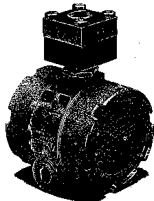
3.Standpipe and choke pressure sensors
1. Strain gauge type:
The Standpipe and Choke Pressure Sensors use a Dynisco strain gauge transducer. The transducer consists of a box of four resistors. An excitation voltage of 15 VDC is applied to one corner and the excitation ground are taken-off from the opposite corner.
The strain gauge resistors are made from silica crystal, which has the property of changing resistance with changing pressure applied across crystal. Note that in essence, the sensor contains two resistor divider networks with the two signal wires in the middle of each. One side has a fixed resistance and thus a fixed output (signal-) while the other has a variable resistance which results in a variable output (signal+).
The signal conditioner card provides the 15 VDC excitation voltage and an amplifier circuit to produce a 0-10 VDC signal to the computer.
The only difference between the standpipe and choke sensors is the type of transducer fitted. All sensors are tested to 15,000 psi.
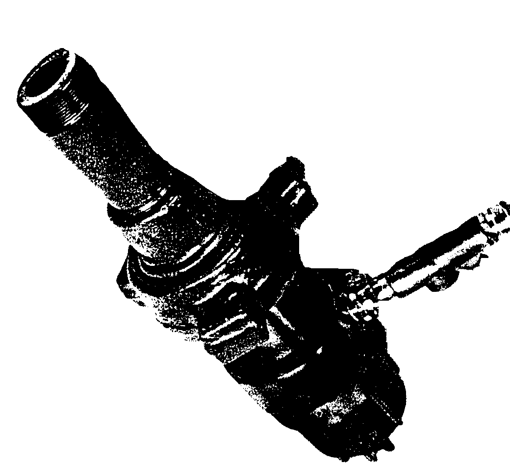
2. Current loop type:
This sensor measures the mud pressure by a direct contact with a pressure transducer. The standpipe sensor has 0-6000 psi transducer is normally specified. Both types of transducer are located in a housing with WECO knockon connector rated for 15,000 psi working pressure.
The transducer normally uses 24 VDC excitation and its output is 4-20 m.a. .
The transducers normally used are either Dynisco 4 wire PT11 ,or in the case of the North Sea Dynisco PT 386 two wire 4-20 m.a. transmitter.
PT 11 sensor mounted on choke manifolds rated for 15,000 psi test/working pressures will require a hydraulic tie-in to the rig’s pressure debooster on the manifold and a 0-6000 psi sensor connected into the debooster line.
For 15,000 psi working pressure choke manifolds, the Dynisco PT 386 0-15,000 psi sensor can be supplied to special order.
In some situations it may be necessary to tie-in to the Martin Decker pressure converters on the standpipe or choke manifold. The Rosemount E 1144 transducer (similar to the Hookload sensor) is usually used for this application.