Semi-submersibles
A semi-submersible is a floating drilling rig. A typical layout is shown below in figure 03.
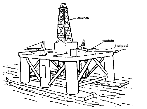
Figure 03
The following are some advantages and disdvantages of Semi-submersibles:
Advantages
Has a good safety record.
Provides a relatively stable platform.
Can function under more severe weather conditions.
Can drill in deep water - up to 2000 ft.
Can be self-propelled.
Disadvantages
Requires marine risers and a sub sea stack.
Has a limited cargo capacity.
Requires support vessels.
Drill ships
These are special types of ships that are built for deep water drilling. They range in length between 200-450 feet. Their cargo carrying capacity and general mobility make them especially useful for drilling in remote areas. An example is shown in( figure 04) below.

Figure 04
Some advantages and disadvantages of drill ships are:
Advantages
High carrying capacity.
Can drill in remote areas.
Can operate in deep water.
Self propelled.
Disadvantages
The lack of suitable risers to support drilling mud circulation between well head and drilling floor.
Not as stable as jackups and semi-submersibles.
requires a subsea stack.
D. Platform rigs
A platform is a fixed installation offshore from which development drilling and petroleum production is carried out. A steel platform design is shown as an example in figure 05 below.
The deck, supported by a steel jacket, carries equipment, accommodation modules and a helicopter pad (helideck). It also supports one or more drilling rigs with associated equipment.
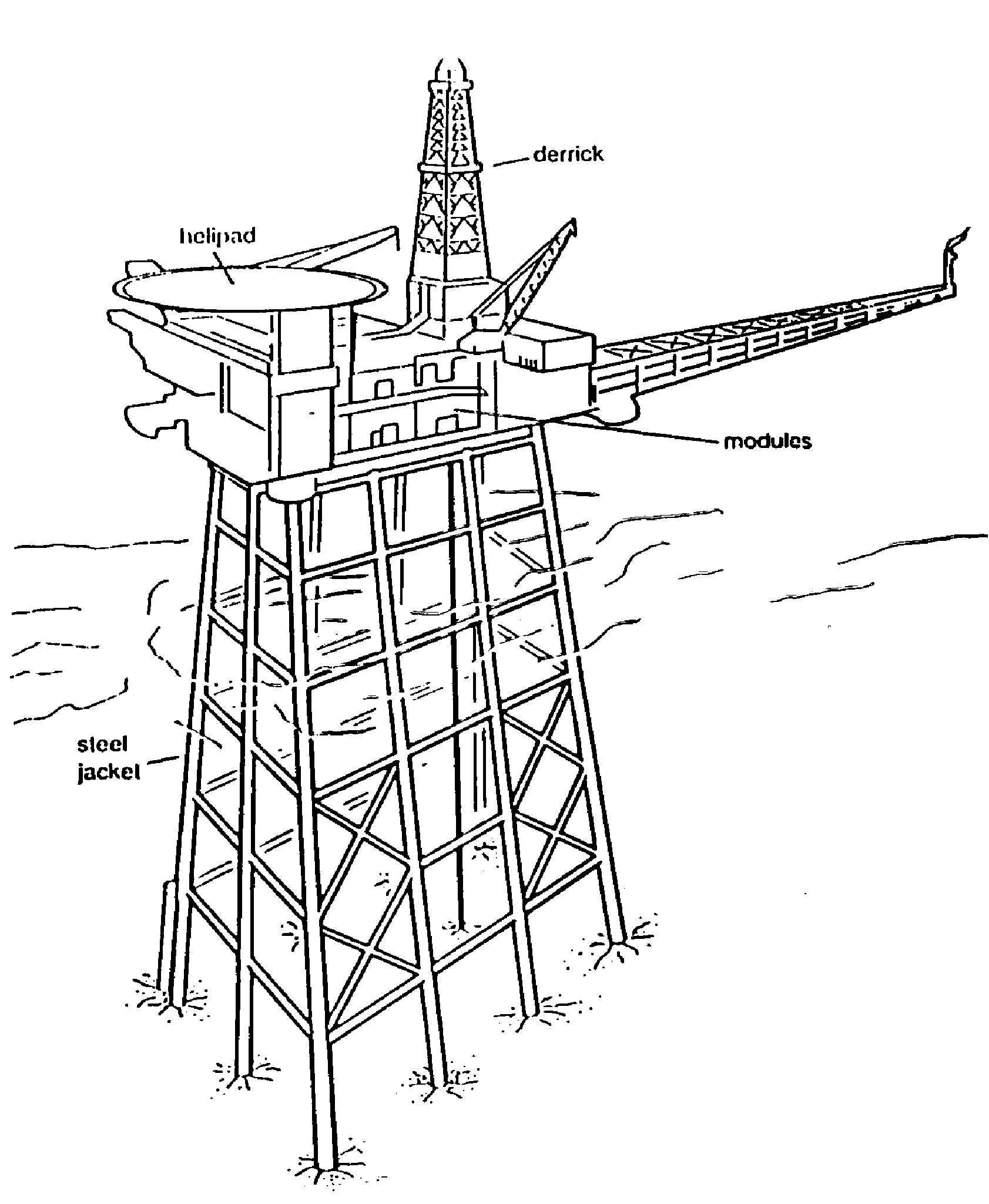
Figure 05
The drilling types
The basic function of a drilling rig is to drill a bore hole. This hole must be drilled in an accurate, economic and safe way. Drilling rigs are of two main types: rotary and cable tool.
Rotary drilling:
The rotation is generated either by a rotary motor to a rotary table or a top drive motor that directly rotates the drill string. The rotary table transfers power to the bit via the rotary and kelly bushings. Weight is supplied by allowing a small amount of the drill string weight to rest on the bit.
Cable tool drilling:
With the wireline method, a cable is used to connect the bit to the surface and a pounding motor is used to effect the weight on the bit.
RIG COMPONENTS
Rigs are made up of various components. However the following discussion is restricted to land rig components, most of these components are also found offshore.
Jack up rigs and fixed platforms are very similar to land rigs. They are not subject to wave and tidal movements as being fixed in relation to the sea bed during drilling operations. Therefore, they have no need for heave components or sub sea stack BOP’s.
In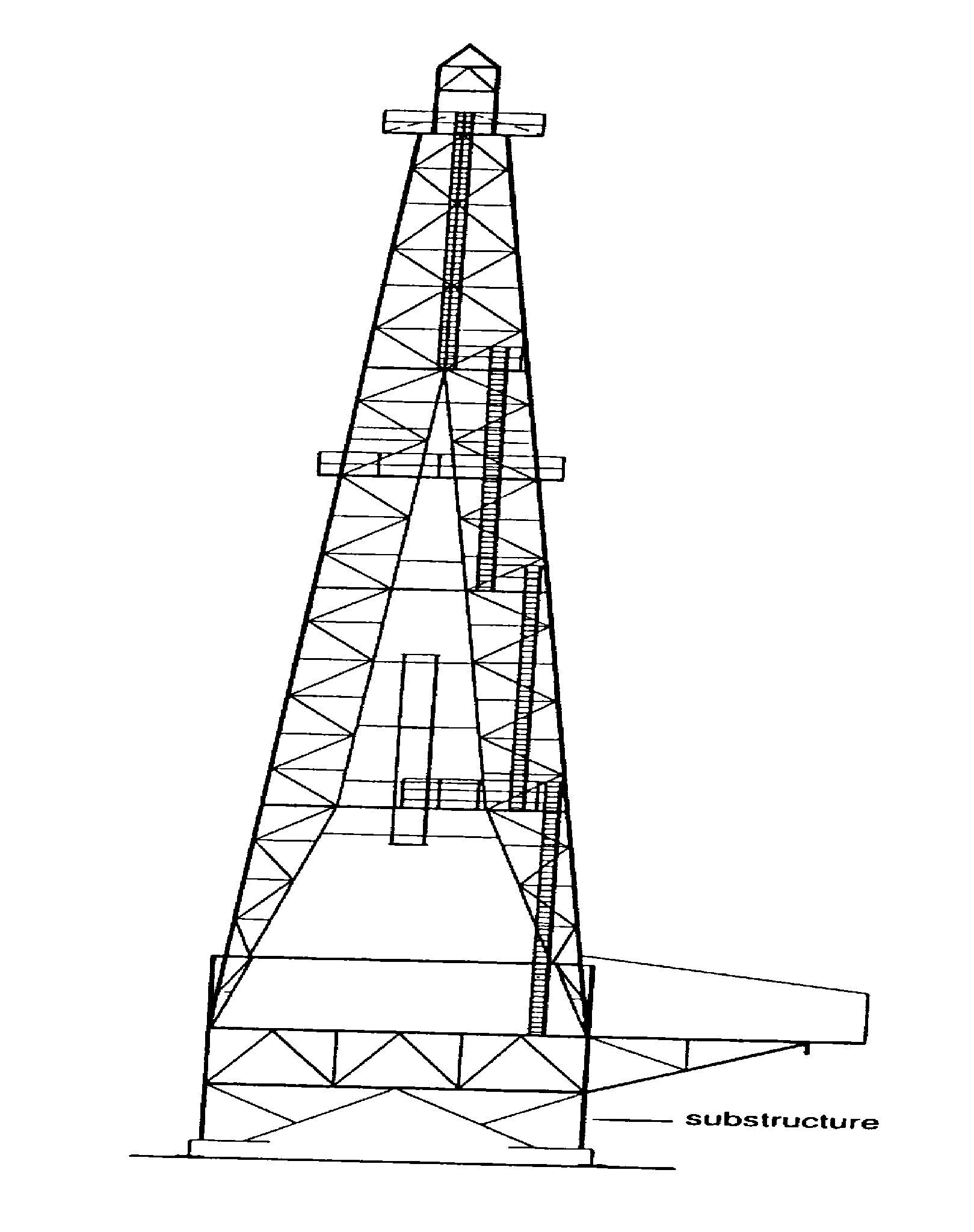 the following few pages we will discuss the main components of
drilling rigs taking land rigs as an example.
the following few pages we will discuss the main components of
drilling rigs taking land rigs as an example.
Land rig components
1. Mast or Derrick
a) Masts
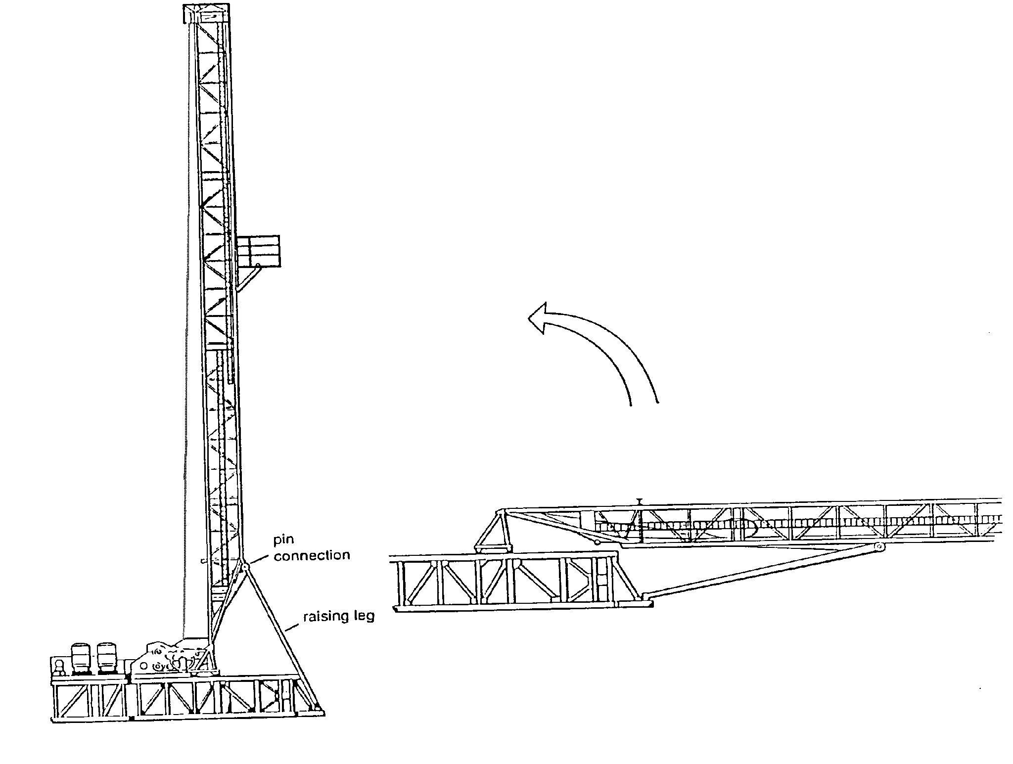
Masts are assembled on the ground from large welded sections fastened together with pins. They may then be raised to the vertical position by using the rig’s own power unit and hoisting line. Small masts may be truck mounted while some are telescopic. This rigging-up time for masts tends to be less than that for conventional derricks.
Rigging-up time is the time spent to assemble a mast into the vertical position on-site. It also includes the time to install the power unit, all cables and piping. Masts are used for lighter work. Cantilever masts (also known as jack-knife derricks) are also common. Figure 06 shows a typical mast layout. (Fig. 06)