

Cement Figure 30
A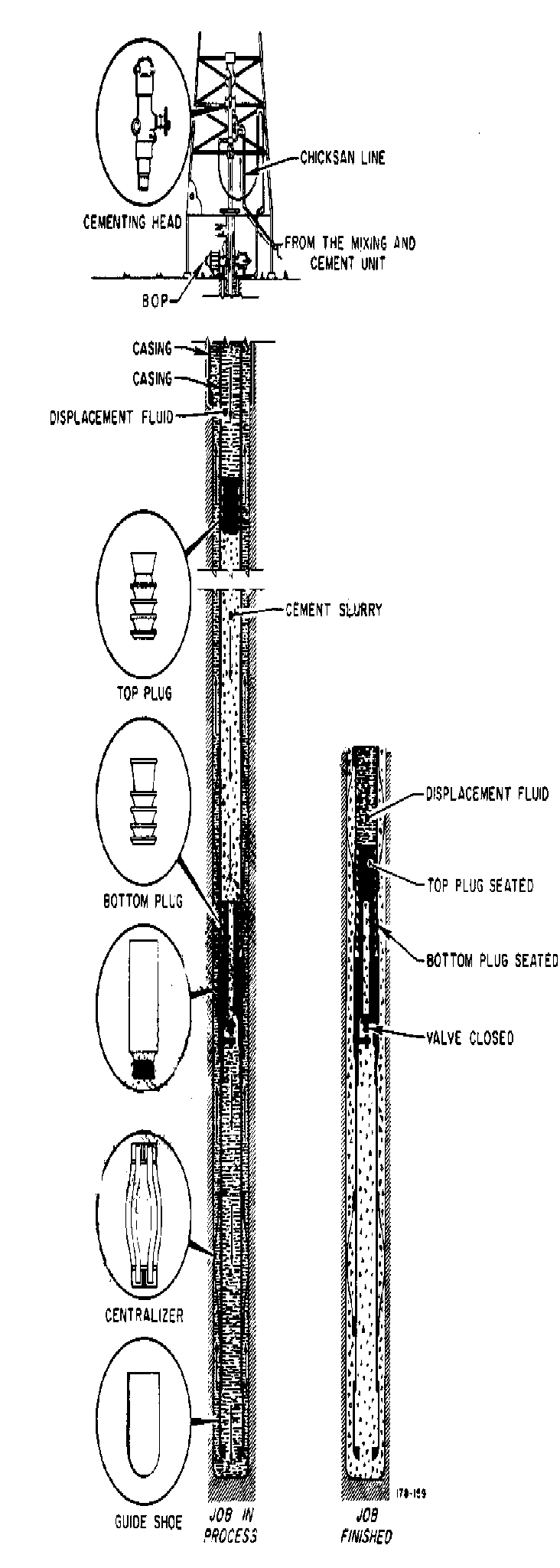 fter
the casing string is run, the next task is cementing the case in the
place. An oil well cementing service company is usually called-in for
this job, although, as when casing is run, the rig crew is available
to lend assistance.
fter
the casing string is run, the next task is cementing the case in the
place. An oil well cementing service company is usually called-in for
this job, although, as when casing is run, the rig crew is available
to lend assistance.
Cementing service companies stock various types of cement and have special transport equipment to handle this material in bulk.
Bulk cement storage and handling equipment is moved out to the rig. making it possible to mix large quantities of cement on site. The cementing crew mixes the dry cement with water, using a device called a job mixing Hopper. The dry cement is gradually added to the hopper and a jet of water thoroughly mixes with the cement to make a slurry (very thin, watery cement). Weighted slurries are often used to insure a control of the formation pressure.
Special (cement) pumps pick up the cement slurry and send it up to a valve called a cementing head (also called a plug container) mounted on the topmost joint of casing that is hanging in the mast or derrick a little above the rig floor.
Just before the cement slurry arrives a rubber plug (called the bottom plug) (Figure 31) is released from the cementing head and precedes the slurry down the inside of the casing. A pre-calculated volume of cement that is equal to the annular volume between casing pipe and hole is then pumped-in, then a top plug (Figure 31) is released from the circulation head and soon mud is pumped behind the top plug -usually with the rig pump to drive the cement to the annulus; This process is called “Cement Displacement”.
The bottom plug stops or “seats” in the float collar, but continued pressure of pumps ruptures a passageway through the bottom plug, thus the cement slurry passes through it and continues on down the casing. The slurry then flows out through the opening in the guide shoe and starts up the annular space between the outside of the casing and walls of the hole. By the time the top plug seals on or “bumps” the bottom plug in the float collar; pump pressure increased sharply which signals the pump operator to shut-off the pumps, the cement is only in the casing below the float collar and in the annular space and the rest of the casing is full of displacing mud.

After the cement is run, a waiting time is allowed to allow the slurry to harden. This period of time is referred to as Waiting On Cement or simply “WOC”.

After the cement hardens, tests may be run to ensure a good cement job, for cement is very important. Cement supports the casing so the cement should completely surround the casing; this is where centralizers on the casing help. If the casing is centred in the hole, a cement sheath should completely envelop the casing. Also cement seals-off formations to prevent fluids from one formation migrating up or down the hole and polluting the fluids in another formation. For example, cement can protect a freshwater formation (that perhaps a nearby town is using as a drinking water supply) from saltwater contamination. Further, cement protects the casing from the corrosive effects that formation fluids (as salt water) may have on it.
After the cement hardens and tests indicate that the job is good, the rig crew attaches or nipples up the blow-out preventer stack on the top of the casing. The BOP slack is then pressure tested and drilling is resumed.