

Wireline logging (electric) logging
A valuable technique for evaluating a borehole is the wireline well logging.
An electric logging company is called to the well while the crew trips out all the drill string. Using a laboratory, truck-mounted for land rigs and permanently mounted on offshore rigs the loggers lower devices called logging tools (or sonde's) into the well on wireline. The tools are lowered all the way to bottom and then reeled slowly back upwards. As the tools are coming up the hole they are able to measure the properties of the formations they pass.
So me
logs measure and record natural and induced electricity in
formations. Other log pings formations with sound and measure as well
as record sound reactions. Radioactivity logs measure and record the
effects of natural and induced radiation in the formations. These are
only a few of many types of E-logs available.
me
logs measure and record natural and induced electricity in
formations. Other log pings formations with sound and measure as well
as record sound reactions. Radioactivity logs measure and record the
effects of natural and induced radiation in the formations. These are
only a few of many types of E-logs available.
Since all the logging tools make a record, which resembles a graph or an electrocardiogram (EKG). The records, or logs can be studied and interpreted by an experienced geologist to indicate the existence of oil or gas and how much may exist. Computers have made the interpretation of logs much easier.
Casing
Casing is steel pipe placed in an oil or gas well at the end of every drilled phase, and then cemented in place prior to striating drilling the lower smaller hole section. See figure 28
(Figure 38) Cross Section shows Casing Profile
FUNCTIONS OF CASING:
Prevents the hole from caving or collapsing.
Prevents loss of drilling fluids into weak formations.
Isolate troublesome formations.
Prevents communication between formations.
Provides means of extracting hydrocarbons if the well is productive.
To effect a method of control and safety as depth increases.
Provides a means of support for the well head equipment.
Once the drill pipe is out, the casing crew moves in to do their work., the first string of casing they run is called surface casing. Other strings of casing include intermediate (or protective) and production casing. A short string of casing called a “liner” may be hung-off from another string instead of extending up to the surface. Running casing into the hole is very similar to running drill pipe, except that the casing diameter is much larger and thus requires special elevators, tongs and slips to fit it.
Casing Accessories
To lower an open ended pipe in an open hole for great depths could be a difficult process, the pipe would tend to dig into the formation as it is lowered. Also casing may tend to lie to one side of the hole,...etc. In order to overcome such difficulties and to assist in the placement of the cement a number of items or equipment are used; these are called “Accessories”.
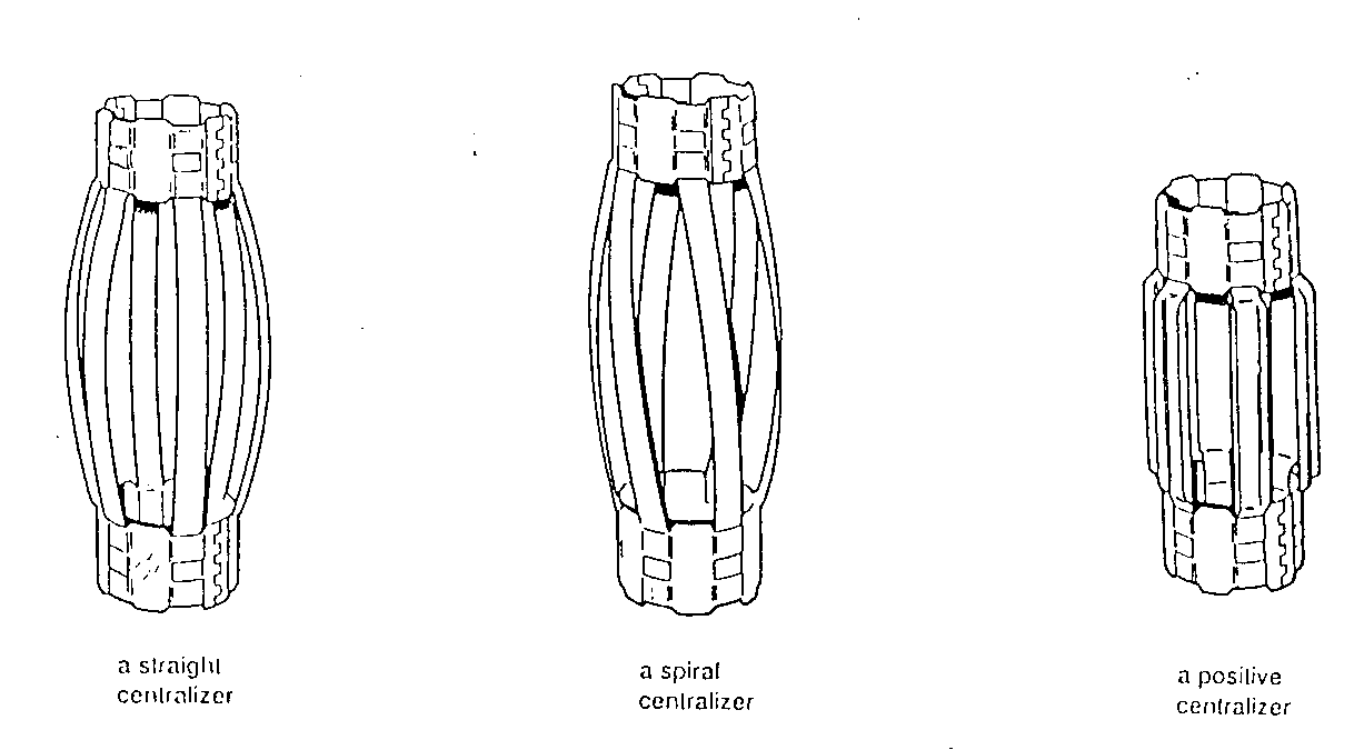
A number of centralizers and scratchers are often installed on the outside of the casing before it is lowered into the hole.
The centralise are attached to the casing and since they have a bowed spring arrangement keep the casing centred in the hole after it is lowered in. Centralised casing can make for a better cement job later.
Th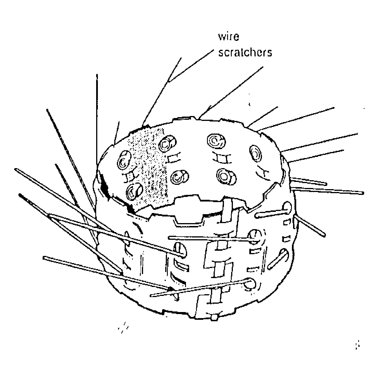 e
scratchers
also came into play when the casing is cemented. The idea is that if
the casing is moved up and down, or rotated (depending on scratchier
design) the scratchers will remove the wall cake formed by the
drilling mud and the cement will thus be able to bond better to the
hole.
e
scratchers
also came into play when the casing is cemented. The idea is that if
the casing is moved up and down, or rotated (depending on scratchier
design) the scratchers will remove the wall cake formed by the
drilling mud and the cement will thus be able to bond better to the
hole.
Other casing accessories include:
A float collar; a device with a valve, installed in the casing string two or three joints from bottom. A float collar is designed to serve as a receptacle for cement plugs and to keep drilling mud in the hole from entering the casing. Just as ship floats in water, casing floats in a hole full of mud )if mud is kept out of the casing). This buoyant effect helps relieve some of the weight carries on the mast or derrick as the long string of heaving casing hangs suspended in the hole. Alternatively the casing may be allowed to fill up to avoid the
p
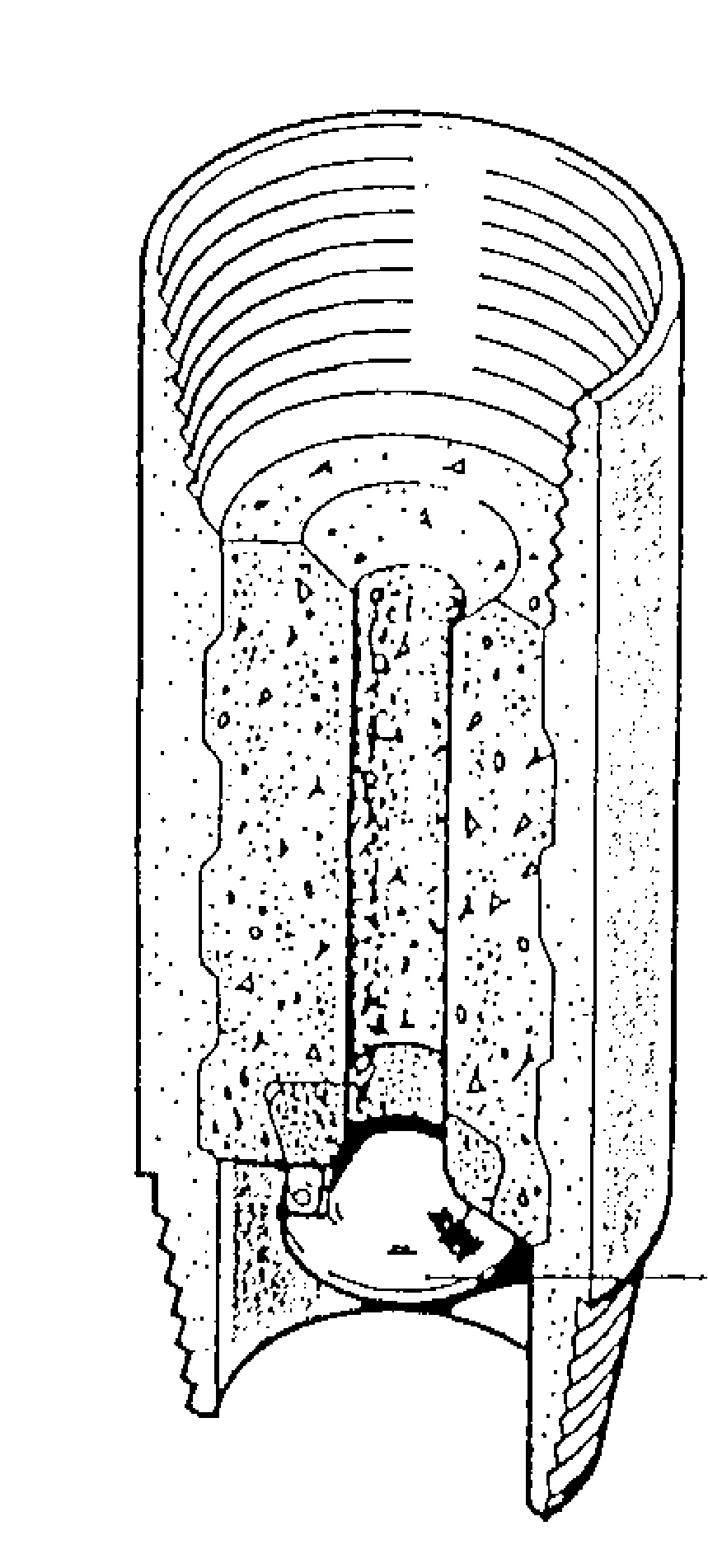
 ossibility
of collapsing the casing at greater depths. This is affected by a
surface or automatic filling via differential fill - up float shoe.
ossibility
of collapsing the casing at greater depths. This is affected by a
surface or automatic filling via differential fill - up float shoe.
A guide shoe; a heavy steel - concrete piece attached to the bottoms joint of casing that helps guide the casing past small ledges or debris in the hole .