

Composition and nature of drilling muds
Water or oil are satisfactory drilling fluids in many instances. Generally, the functions to be performed require mud properties which can not be obtained from ordinary liquids. A typical mud consists of:
(1) A continuous phase (liquid base)
(2) Dispersed gel-forming phase such as colloidal solids and/or emulsified/ liquids which furnish the desired viscosity, thixotropy and wall cake.
(3) Other inert dispersed solids such as weighting materials, sand and cuttings.
(4) Various chemicals necessary to control properties within desired limits.
Types of mud
The most common types of the drilling mud are the following:
1- Fresh water mud
2- Calcium treated fresh water mud
3- Salt Saturated mud
4- Oil base mud
Mud Properties Termenology
The following is a brief explanation of the mud data on the ADT morning report.
De nsity
Density ( weight) : Any accepted terminology that indicated the weight per unit volume of a drilling fluid that may be used to determine the hydrostatic pressure exerted by that fluid. It is measured in three basic ways, they are as follows : Pounds per gallon, pounds per cubic foot and specific gravity.
Th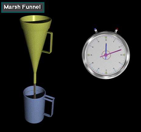 e
effects of density are as follows : Hydrostatic pressure, pressure
differential on the formation, and therefore, drilling rate,
hydraulics, circulating pressure, lifting capacity and hole cleaning,
flow pattern ( laminar or turbulent) stability of pressured
formations.
e
effects of density are as follows : Hydrostatic pressure, pressure
differential on the formation, and therefore, drilling rate,
hydraulics, circulating pressure, lifting capacity and hole cleaning,
flow pattern ( laminar or turbulent) stability of pressured
formations.
Rheology
Rheology ( viscosity at all shear rates) : All the characteristics that define the flow and gelation properties of a drilling fluid.
Funel Viscosity
Is a routine field measurement of the viscosity of drilling fluid are made with a marsh funnel. This measures a timed rate of flow in seconds per quart under specific gravit free fall. The values obtained are called “apparent” viscosity.
Plastic viscosity:
i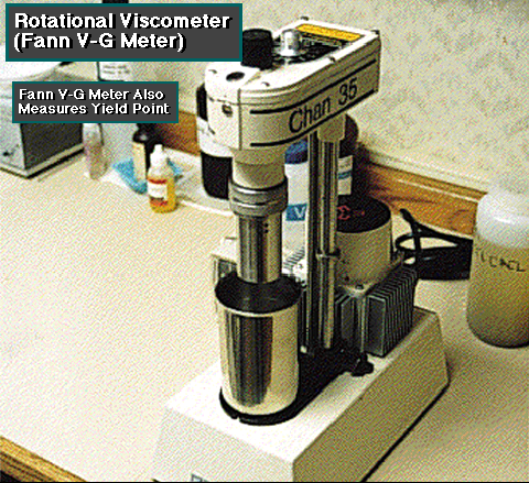 s
that part of flow resistance in a mud caused primarily by the
friction between the suspended particles and by the viscosity of the
continuous liquid phase. For practical purposes plastic viscosity
depends on the concentration of solids present and the size and shape
of these solid particles.
s
that part of flow resistance in a mud caused primarily by the
friction between the suspended particles and by the viscosity of the
continuous liquid phase. For practical purposes plastic viscosity
depends on the concentration of solids present and the size and shape
of these solid particles.
Yield point:
is a measurement under flowing conditions of the forces in the mud which cause gel structure to develop when the mud is at rest. These forces exist between the solid particles, and are the result of positive and negative electrical charges located on or near the surface of each particle. When the mud is at rest, the solid particles tend to arrange themselves in such a manner that these attractive and repulsive forces are best satisfies.
Gel strength:
i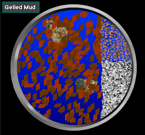 s
a rheological property of a drilling fluid at rest. Drilling mud has
gel strength when a force is required to start the mud moving. Gel
strength arises mainly from attraction between particles and from
friction between solids in suspension or between the solids and the
liquid around them. Gel may be progressive in that gel strength may
increase continuously for a long period of time, while the gel
strength of other muds may reach a near-maximum in a brief time
intght alkalinity to 14 for the stronger alkalinity while acid
solutions range from just below 7 for slight acidity to less than 1
for the strongest acidity.
s
a rheological property of a drilling fluid at rest. Drilling mud has
gel strength when a force is required to start the mud moving. Gel
strength arises mainly from attraction between particles and from
friction between solids in suspension or between the solids and the
liquid around them. Gel may be progressive in that gel strength may
increase continuously for a long period of time, while the gel
strength of other muds may reach a near-maximum in a brief time
intght alkalinity to 14 for the stronger alkalinity while acid
solutions range from just below 7 for slight acidity to less than 1
for the strongest acidity.
pH :
measurement is used as an aid in determining the need for chemical control of mud as well as indicating the presence of contaminates such as cement, gypsum etc.
There are two common methods of obtaining this value. The pHydroin dispenser which provides a series of paper indicator strips that determine pH from 1 to 14. Changes in color or color identify over the range of each indicator should be sufficient to allow the operator to read to within 5 pH units. The other method is the pH meter. The meter will measure the pH within 1pH units.