

3.The drilling mud
Following is a short section on the purposes of a drilling mud. These are briefly to:
Clean the bottom of the hole.
Cool the bit and lubricate the drill stem.
Transport the cuttings to the surface.
Support the walls of the hole;
Prevent entry of formation fluids into the well.
Transport the bottom hole conditions to the surface.
Transport the (MPT) Mud Pulses Telemetry to the surface.
Ot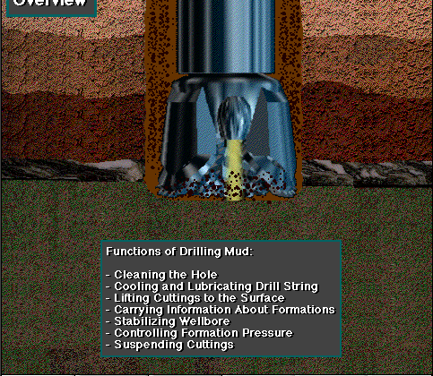 her
purposes of the drilling fluid are to permit the detection gas, oil
or water that may enter the wellbore from a formation being drilled,
and to transmit power to the bit. In addition, drilling fluid is
sometimes used to drive a turbodrill or downhole motor that has been
placed at the bottom of the drill stem. In this case, the drilling
fluid provides power to the motor so that the bit turns without
engaging the rotary table.
her
purposes of the drilling fluid are to permit the detection gas, oil
or water that may enter the wellbore from a formation being drilled,
and to transmit power to the bit. In addition, drilling fluid is
sometimes used to drive a turbodrill or downhole motor that has been
placed at the bottom of the drill stem. In this case, the drilling
fluid provides power to the motor so that the bit turns without
engaging the rotary table.
Purposes of Mud
To clean the Bottom of the hole
A rotary bit must have a clean surface on which to work when making hole, regardless of weather it is crushing or shearing the formation. If the chips or cuttings are not swept away as they are formed the bit bogs down and eventually the drill stem cannot be turned. For the bits to regrind the chips already broken off from the hole bottom is to waste its effort, reducing the power available for making hole. The usual method of cleaning the bottom is by fluid circulation through jet nozzles in the bit. High velocity streams of fluid blast the bottom of the hole creating a turbulence that moves the chips from the face of the formation as fast as they are formed.
Fluid that is pumped back to the bit is clean drilling can be done faster with a light weight fluid than with a heavier liquid the system should also be designed to enable a large volume of liquid under high pressure to reach the bit. the proper combination of pump, drill stem nozzles and hole diameter achieves this by enabling about 50 to 60 per cent of the fluid pressure generated by the pump to reach the bit nozzles and clean the bottom of the hole.
To Cool the Bit and Lubricate the Drill Stem
The bit is pressed against the bottom of the hole very heavily. For example, drilling weight on an 8 1/2 inch bit sometimes exceeds 60,000 pounds (Ib) which is about the weight of a railroad freight car. A large diameter bit might require double that amount of weight. The bit may be rotated at a speed of 50 to 200 revolutions per minute (rpm). This combination of weight and speed creates heat due to friction in the bit bearings and the abrasion of the formation against the teeth or blades. Unless a bit is properly cooled, it overheats and quickly wears out. Fluid circulated around the cones and across the teeth removes the heat as fast as it is generated. Oily substances in the drilling fluid can reduce friction in the bit bearings and act as a lubricant between the drill stem and the Walls of a hole. Oil emulsion mud and oil mud are especially beneficial in this regard. Air or gas circulation is particularly efficient for cooling because the air or gas expands as it leaves the nozzles of a bit, causing a cooling effect. For this reason and because air contains no significant foreign material wear on the bit bearings is much less with this method than with mud circulation.
To transport the cuttings
Th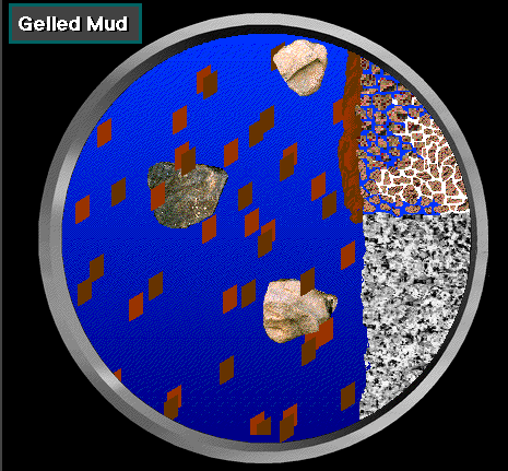 e
liquid, air, foam or gas circulated moves rock chips, sand or shale
particles out of a well as it moves up the annulus. For a liquid, the
annular velocity may range from 50 to 100 feet per minute (ft/min) in
order to keep the hole clean. Circulation of 3000 ft/min is
considered ample velocity in the annulus for cleaning with gas, foam
or air. The solids in the liquid mud are separated from the mud at
the surface by screening, settling, centrifugal action or a
combination of these methods. When drilling with air, foam or gas,
the solid materials are blown as dust or fine chips to a waste pit.
e
liquid, air, foam or gas circulated moves rock chips, sand or shale
particles out of a well as it moves up the annulus. For a liquid, the
annular velocity may range from 50 to 100 feet per minute (ft/min) in
order to keep the hole clean. Circulation of 3000 ft/min is
considered ample velocity in the annulus for cleaning with gas, foam
or air. The solids in the liquid mud are separated from the mud at
the surface by screening, settling, centrifugal action or a
combination of these methods. When drilling with air, foam or gas,
the solid materials are blown as dust or fine chips to a waste pit.
The viscosity of a drilling mud is defined as its resistance to flow. A Marsh funnel is the usual means used to measure apparent viscosity of the mud. The marsh test measures a timed rate of flow that roughly correlates with true viscosity. Funnel viscosity may be from 30 to 40 seconds (s) for low- solids muds, from 40 to 50 (s) for a high-solids muds and above 50 (s) for heavier muds. The viscosity and Gel strength(Gel strength is the ability of a mud to tend to solidify or gel when it is not in motion- when it is pumped it thins) of a drilling mud are increased by the addition of clay or bentonite. Conversely, water or chemicals can be added to reduce viscosity and gel strength. Gel strength - whether low, medium or high - can be observed from the way the mud flows and stiffens in the ditches and pits. Drilling muds are subject to wide variations but it is relatively simple to develop enough gel strength in a water-base mud to suspend cuttings and particles of normal specific gravity (weight) in the hole when circulation is stopped.
To Support the walls of the Well
A drilling fluid with the proper characteristics can support a formation that might otherwise cave into a well. This type of drilling fluid, plasters the walls of a well like a mortar. The hydrostatic pressure created by the weight of the fluid column in the hole pushes against the plastered wall to support unconsolidated or lease formations that might tend to fall or slough into the well. hard-rock formations usually do not have this tendency to slough and can be drilled with air, gas or water instead of mud. Hydrostatic pressure (force) against the sides and bottom of a hole is caused by the weight of the fluid above that point in the well; it is determined by the unit weight or density of the fluid and the height of the column of fluid (that is, the depth). An increase in the hydrostatic pressure at any depth can be obtained by increasing the density of the fluid, a process usually accomplished by adding finely ground barite to the mud. Barite is a mineral that is 4.3 times heavier than water.
The weight of drilling mud is measured by means of a mud balance. mud weight is commonly expressed in terms of pounds per gallon (ppg), pounds per cubic foot (pcf), kilograms per litre (Kg/Lt) or gram per cubic centimetre (g/cc) which is The same as the specific gravity. Pounds per square inch (psi) of pressure per thousand feet of head, that is. hydrostatic pressure, is also used to express mud weight. Hydrostatic pressure may be roughly estimated at about 1/2 psi for each foot of depth with mud weighing 10 ppg (75 lb/ft 3). In the metric system a mud weighing 1.2 kg/litre exerts about 11.7 kpa for each metre (m) of depth; Pressure is expressed in Pascal, Kilopascals or Megapascals Hydrostatic pressure can be calculated by using one of the following expressions:-
HYDROSTATIC PRESSURE (PSI ) = depth (ft) x mud weight(ppg)x0.052, or
HYDROSTATIC PRESSURE (PSI ) = depth (ft) x mud Weight(lb/ft3)x0.00695, or
HYDROSTATIC PRESSURE (MPa ) = depth (m) x mud Weight(kg/lt)x0.00980
Filter cake, the plaster-like coating formed from mud on the walls of a well, has the ability to seal the wellbore and prevent the loss of fluid. Filter cake is formed by fluid pressure against the sides of the wellbore, which causes the solids to be separated from the liquid- particularly in those areas in which there is a permeable section in the well. the force of the hydrostatic pressure literally squeezes the liquid phase of the mud (the filtrate) into the permeable zones and the solid material is left behind as a filter cake.
This filtration slows to a very low rate when a thick filter cake has been formed on the walls of a well. Finely ground clays or other substances are added to a drilling fluid to improve its wall-building quality, that is, its ability to form a filter cake Measurement
by means of a filter press of the amount of filtrate that accumulates when a mud is tested helps indicate the wall-building quality of that mud.
Certain difficulties may arise if the fluid loss of a mud becomes excessive. First the filter cake may become thick enough to reduce the diameter of the hole, thus causing tight intervals in the hole and even sticking the drill-stem. Second, muds with a high fluid loss tend to cause sloughing and caving of shale formations due to the entry of filtrate into the formations Third, filtrate entering the productive zones may make it difficult to complete the well.
To Prevent Entry of Formation Fluids into the Well
The pressure of gas, oil or water in formations penetrated by the bit may exceed the hydrostatic pressure of the fluid column in a well. If this happens, formation fluid enters the well unless back pressure is held on the column at the surface or heavier mud is circulated in order to obtain enough pressure at the bottom of the hole to overcome the formation pressure.
The addition of weighting materials to the mud being circulated in a well can make a mud heavy enough to hold back almost any formation pressure. when formation pressures are expected to be high a high mud weight is needed and the pits and other equipment should be especially arranged to handle the heavy mud. A mud weight of 16 to 18 ppg (120 to 135 Ib/ft3, or 1.92 to 2.16 g/cc) is considered heavy.
The special valves and fittings at the well head, called blowout preventers, are for emergency control when formation fluids enter the hole. They are used to close in the well and allow mud of a weight heavy enough to control the pressure to be circulated. Maintaining the proper mud weight and carefully controlling other mud characteristics are the best ways to prevent blowouts. Although this lesson does not deal with the technique of killing a threatened blowout, the new man on the rig should know the signs of an upcoming blowout. The first sign of a blowout is an increase in the volume of fluid returning from the hole. Also when a blowout is about to occur, mud continues to flow from the well when the pump is shut down and a volume gain in the mud pits is observed.