

29. Bop’s (Blow-Out Preventers)
Th e
main function of the blow-out preventers is to furnish a means of
closing-off the annular space between the drill pipe and casing. Most
preventers are either hydraulically or pneumatically controled with
manual operation available as a safety precaution. Blow-out
preventers are rated according to their working pressure and their
inner diameter. There are many design variations of BOP’s; however,
they fall essentially into two categories :
e
main function of the blow-out preventers is to furnish a means of
closing-off the annular space between the drill pipe and casing. Most
preventers are either hydraulically or pneumatically controled with
manual operation available as a safety precaution. Blow-out
preventers are rated according to their working pressure and their
inner diameter. There are many design variations of BOP’s; however,
they fall essentially into two categories :
A) Annular Preventers:- This type seal by closing a circular packing element around the drill pipe; this element is made of rubber one most types will also seal the annulus with virtually anything or nothing in the bore. (Figure 24)
B) Ram Preventers:- These derive their name from the hydraulic cylinders and ram shafts that move the two sealing ram blocks. (Figure 25)
Unlike annular preventers, this type will only seal around a specific pipe size; to accommodate different pipe sizes the ram elements are changeable.
A set of rams and annual preventers, when assembled, is known as the Blow-Out Preventer Stack; commonly referred to as the stack or BOP’s (Figure 26).
Ram Type BOP
Figure 25

Example of BOP Stack Arrangement
Figure 26

Rig personnel
Company Man or Company Representative:
The operator representative usually a drilling engineer employed by the oil company engaged in drilling.
Tool Pusher:
A drilling foreman or rig superintendent.
Driller :
Employee in charge of the “brake” responsible for making hole as quickly as possible.
Assistant Driller:
Assists driller in “making hole” and general jobs around the rig.
Derrick Man:
Responsible for stacking pipe in derrick during trips. Operates from monkey board attached by safety harness. Assist mud engineer to mix mud.
Roughnecks/ Floor hands:
General workers under supervision of the driller.
Rig Mechanic :
Keeps the rig running smoothly. Controls maintenance of rig.
Motorman Rig Electrician Rig Welder:
Keep the motors running.
Mud Engineer:
Controls properties of drilling fluid within limits specified by operator.
Mud Loggers :
Produce mud log of the well. Responsible for detecting changes in volume of surface mud, changes of drilling parameters and the presence of hydrocarbons.
Offshore Personnel
Captain :
Responsible for the rig as a marine vessel. He will hole a masters certificate, and is in command during rig moves.
Crane Operators:
Re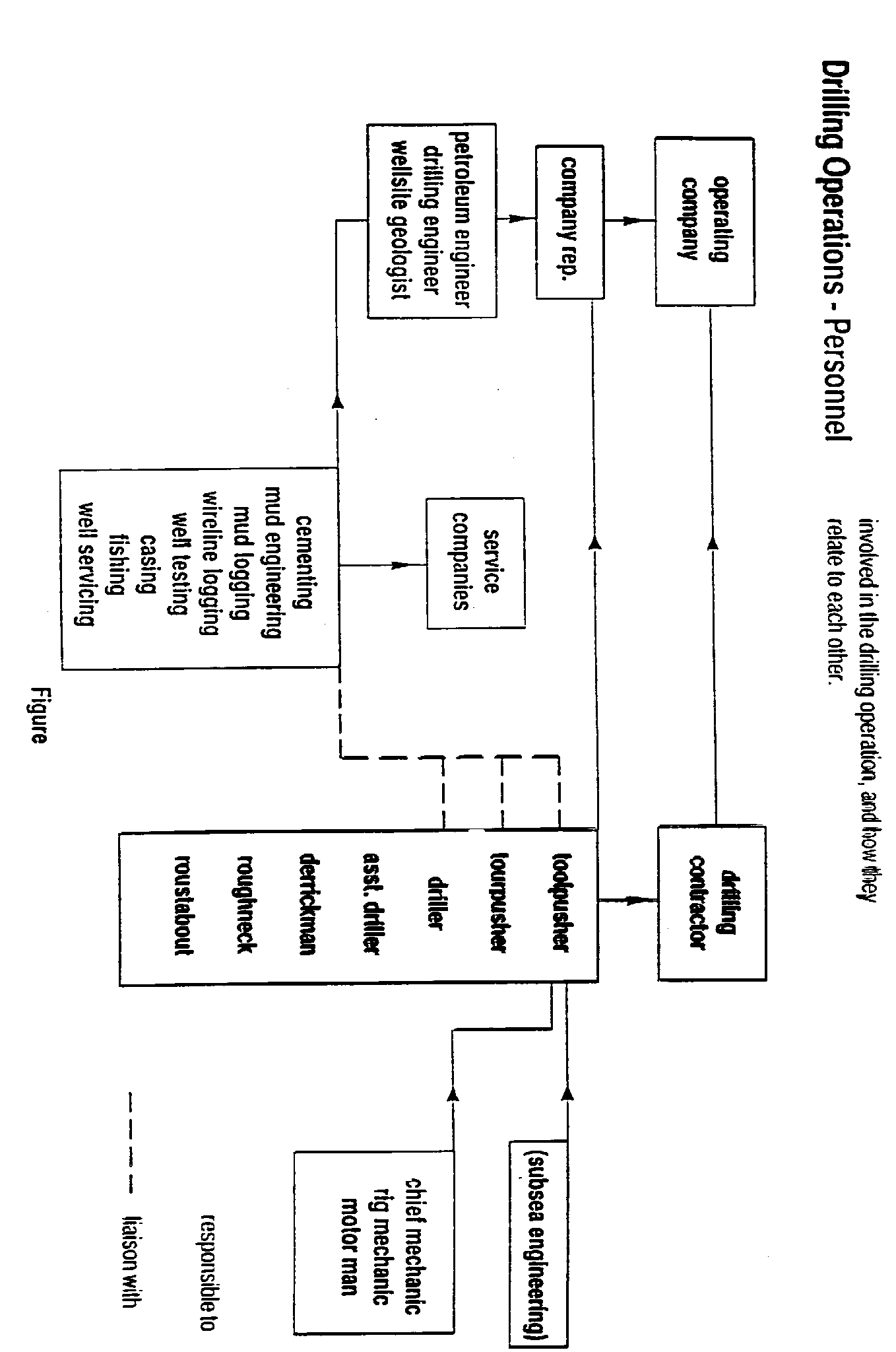 sponsible
for loading and unloading of supply boats. Usually doubles as a
roustabout supervisor.
sponsible
for loading and unloading of supply boats. Usually doubles as a
roustabout supervisor.
Barge Engineers:
Responsible for the vessels stability and rig move.
Radio Operator
Operates radio to communicate rig to town.
The relationships between all of the previous mentioned personnel can be explained by using a simple organization chart. On the chart on the next page, the solid lines show lines of responsibility. The broken lines show where there is liaison between the companies or departments.
It is realised that this organization chart is a hypothetical one, actual company organisation may vary slightly from this.
The services provided by the service companies which are listed in the chart will be covered through the rest of the units.