

Rig types & components rig processes
June, 2002 Contents
1. WELL PLANNING 3
1. Operating company 4
2. Drilling contractor 4
3. Drilling service companies 4
4. Logistical support services 4
5. DRILLING PROGRAMME 4
2. RIG TYPES & COMPONENTS 6
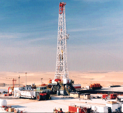
6. LAND RIGS 6
7. OFFSHORE RIGS 7
a)JACK-UP RIGS 7
b)SEMI-SUBMERSIBLES 8
c)DRILL SHIPS 9
8. D. PLATFORM RIGS 10
9. THE DRILLING TYPES 11
10. LAND RIG COMPONENTS 11
11. RIG PERSONNEL 35
3. THE DRILLING MUD 41
12. TYPES OF MUD 45
13. Mud Properties Termenology 45
Density 45
Rheology 46
Funel Viscosity 46
Plastic viscosity: 46
Yield point: 46
Gel strength: 47
pH : 47
Filtration 47
Alkalinity 48
Chloride Content 48
Calcium 48
4. RIG PROCESSES 48
14. Drilling 49
a) Normal drilling : 49
(b)Directional Drilling 50
(c)Drilling to total depth (TD) 51
15. Coring 51
(a)Conventional coring: 51
(b)Sidewall coring 51
16. Tripping 51
17. STUCK PIPE 58
18. Fishing 62
19. Wireline logging (electric) logging 64
20. Casing 64
21. Cement 67
22. Completing the well & Setting Production Casing 69
23. Perforating production casing 69
24. Drill Stem Test (DST) 69
25. Acidizing 70
26. Fracturing 70
27. Installing the Christmas Tree 70
5. Mud Logging Definition 72
28. TYPES OF MUD LOGGING UNITS 73
29. DUTIES & RESPONSIBILITIES 75
6. THE MUD LOGGING THEORY & LAG 81
7. Sample collection and description 80
30. Preparation for collection of cutting sample 80
31. Shaker Samples 80
32. Sample Descriptions 83
Rock Types 85
33. DESCRIBING AND LOGGING OIL SHOWS 90
34. Some Criteria & Procedures For Rock & Mineral Identification 95
Testing Methods: 95
35. GENERAL REMARKS ON SAMPLE ESCRIPTION 99
36. CONTAMINATION OF CUTTINGS 99
8. GAS SYSTEM 102
37. Gas Curve 103
38. TYPES OF RECORDED GASES 104
39. GAS DETECTION AND ANALYSIS 106
MONITORING EQUIPMENT 106
GAS TRAP ASSEMBLY 106
40. FID GAS DETECTOR 106
41. FID GAS CHROMATOGRAPH 109
9. SENSORS 110
42. SENSORS SPECIFICATIONS 110
1.HOOK LOAD SENSOR 112
2.TORQUE SENSORS 112
Electric torque type: 112
Mechanical torque type: 113
3.STANDPIPE AND CHOKE PRESSURE SENSORS 113
7.ANALOG ROTARY SPEED SENSOR 114
8.PIT VOLUME SENSORS 115
9.FLOW OUT SENSORS 118
10.MUD TEMPERATURE SENSORS 119
11.MUD DENSITY SENSOR 119
12. MUD CONDUCTIVITY SENSOR 120
13. DEPTH SENSOR 121
14. PUMP STROKE SENSOR 121
15. DIGITAL ROTARY SPEED SENSOR 122
16.GAS TRAP ASSEMBLY 122
17. HYDROGEN SULPHIDE GAS DETECTOR - H2S 123
1.WELL PLANNING
Before a new well is drilled a well plan has to be developed. There is a number of different companies involved in making the hole and a well plan requires close liaison between them.
A little later we will look at the relationship between the different companies but let’s first consider the major bodies involved in the operations.
Operating company
The operating company is the oil or gas company which has a licence to drill for and produce petroleum within a specified area. The actual licence may be held by a number of companies who are working as a partnership. in such a case one of the partners is usually nominated as “the operator”.
Drilling contractor
To do the actual drilling of the well the operator will employ a drilling contractor. Usually, the contractor is the owner of the drilling rig and is responsible for providing the personnel who make up the drilling crew.
Drilling service companies
As you will shortly see, there are many special drilling services required during the drilling of the well. It is the responsibility of the operator to engage these companies and coordinate their activities.
Logistical support services
Supply of equipment, materials and personnel to and from the drill site has to be arranged and coordinated. In offshore, this will involve the use of aircraft, helicopters and supply boats. In Onshore, conventional land transport will be required. Once again it is the responsibility of the operator to organize all this.
The well is drilled in a series of stages. At each stage, different kinds of problems are encountered. It is crucial to try to anticipate these problems in order for the drilling crew to take the necessary measures to minimize their effect.
In order to do this, the operator’s drilling department will collect as much information as possible about the nature of the formations through which the well will be drilled. This information should include:
Expected total depth of the well.
Types and thicknesses of different rock formations to be drilled.
Expected formation pressures.
Depth and nature of any troublesome formations that may be encountered.
If the well is being drilled as a development well in an area where there are other wells, this information is readily available. However, if the well is an exploration well in a new area, the information is scarse and hence, much has to be inferred from the seismic surveys.
Having collected and collated all available data, the drilling department of the operating company will develop the drilling programme.