Step 6: Setup AutoCad® Isometrics
Setting up AutoCAD® Isometric is a big topic and needs a lot of experience. Explaining how to setup AutoCAD® Isometrics can take hours. Therefore I just want to give some hints before you get started.
Most of the configuration is done under the “Isometric DWG Settings” in your Project Setup. In addition to that there is the IsoConfig.xml file which does exist for each Style (e.g. Check_ANSI-B).
If it comes to the matter of creating your own Iso-Symbol you may want to take a look at the IsoSkeyAcadBlockMap.xml and IsoSymbolStyles.dwg in the Isometric folder under your Project Folder.
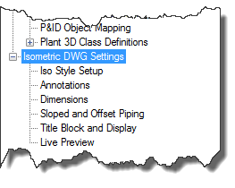
When switching between the different sections of the configuration (Iso Style Setup, Annotations, Dimensions and so on), make sure that you always use the same Iso Style.
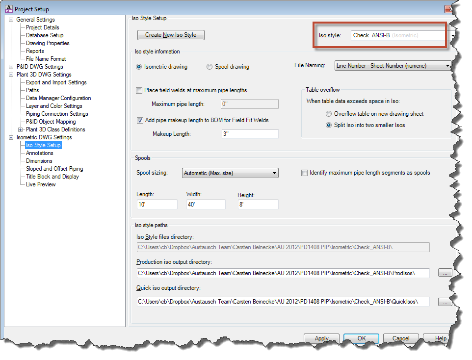
Iso Style Setup sets up the general style of your Iso. You can for example switch to Spooled Isos.
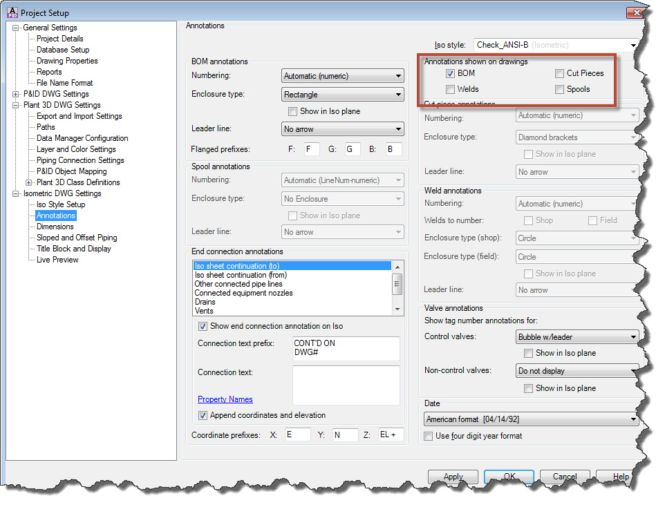
Annotations allows you to setup what should actually be annotated. As soon as you activated one of the checkboxes under “Annotations shown on drawings” the corresponding section on the dialog will be enabled for further setup.
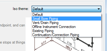
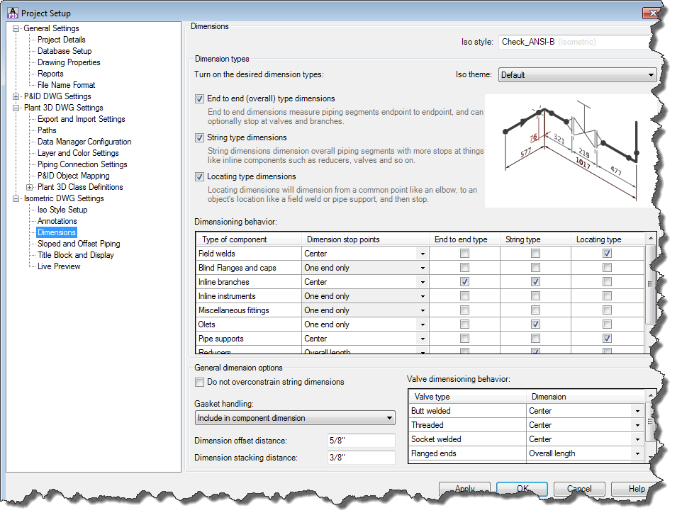
Dimensions allows you to setup the way the objects on the drawing are supposed to be dimensioned. If needed you can select one of the preset Iso themes.
Sloped and Offset Piping allows you to setup the way you want to see sloped and offset piping

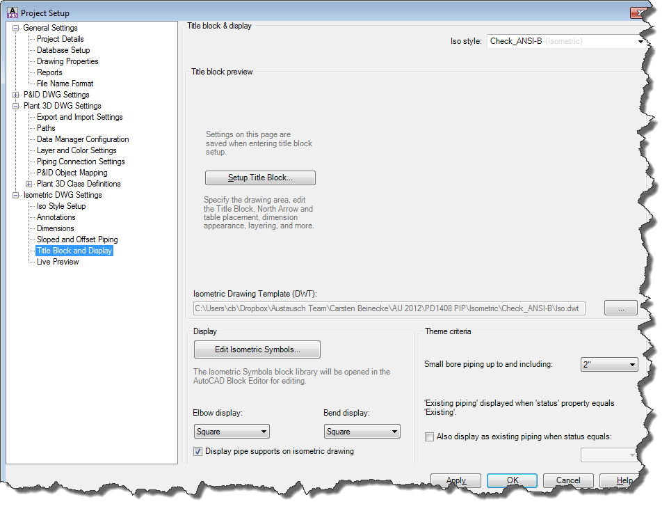
Title Block and Display allows you to setup the Title Block as well as editing the Isometric Symbols.
If you want to make changes to the Iso-Setup bring a lot of time, because you just get lost in the possibilities to adapt it to your requirements.
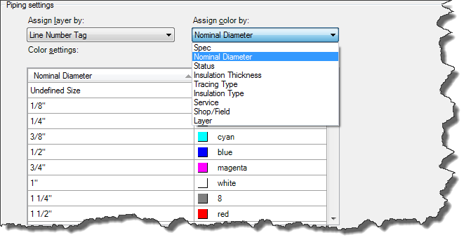
Step 7: Layer & Color Settings
AutoCAD® Plant 3D sets the layer and color of your PipeRunComponents automatically by default. If you want to handle this yourself, you can just turn it off.
Also you can define various Layer/Color Settings. Of course only one can be active at a given time.
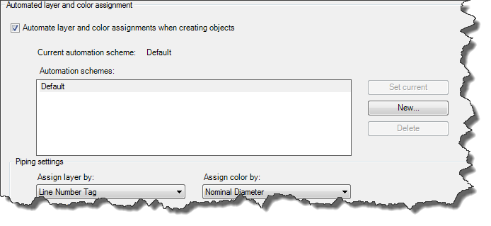
As a Layer you can select any Property of the PipeRunComponent class. You can of course create your own Property just for the Layer Control.
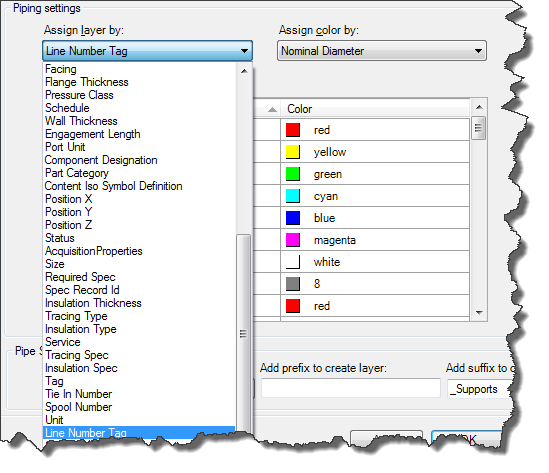
For the Color you can use any selection list. Again you can use your own Property using your own Selection List. For each of the values of your Selection List you can define a color.
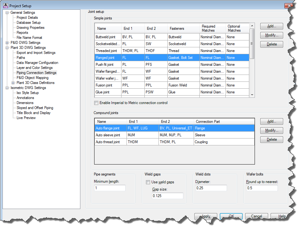
Step 8: Piping Connection Settings
The Piping Connection Settings define the rules on how AutoCAD® Plant 3D Objects have to be put together. This is a topic for very very advanced users. You have to do a lot of testing to make any changes. There is a direct correlation between the port properties of your Pipe Run Components and the settings in this dialog.
For example: If you put a Valve in a Pipe you have two BV/FL connections. Under Compound Joint it says to insert a Flange for each connection. Then the Simple Joints kicks in. Now we have two FL/FL connections. Because of the Simple Joint setting a Gasket and Bolt Set will be inserted in-between the flanges.
So that’s the general idea behind the Joint Setup, but before you make any changes here it is highly recommended that you backup your Project first.
In some occasions you even may have to do some editing in the DefaultConnectorsConfig.xml file which is located in your Project Folder.