How to setup a perfect project for AutoCAD® P&ID and Plant 3D.
Carsten Beinecke – CAD STUDIO ABCOM GmbH, Germany Dinant Weenk – CAD STUDIO ABCOM GmbH, The Netherlands
Code PD1408
Learning Objectives
At the end of this class, you will be able to:
Gather information
Setup AutoCAD® P&ID
Setup AutoCAD® Plant 3D
Installation in a network environment
Manage Data
Make use of Advanced Features
Consider 3rd party solutions
About the Speaker
Selling, Supporting, Training, Developing and Using Autodesk based Plant products since AutoCAD® Release 10 (incl. 3D piping). Writing training manuals in German and English.
Table of Content
Learning Objectives 1
About the Speaker 1
Gather information 4
Setup AutoCAD® P&ID 5
Step 1: Analyze and compute the info from your checklist 5
Step 2: Create classes, properties and selection lists 6
Assets (Symbols and Lines) 6
Project & Drawing Properties 8
Creating Selection Lists 10
Step 3: Define acquisition rules 12
Step 4: Create template drawings (DWT) 16
Step 5: Create Tags and Annotations 18
Creating Tags 18
Creating Annotations & Labels 22
Step 6: Create Symbols & Lines 27
Creating Lines 28
Creating Symbols 29
Setup AutoCAD® Plant 3D 36
Step 1: Analyze and compute the info from your checklist 36
Step 2: Create properties, acquisition rules and selection lists 37
Properties 37
Acquisition Rules 37
Step 3: Create template drawings (DWT) 37
Step 4: Create Tags and Annotations 38
Tags 38
Annotations 39
Step 5: Create Catalogs & Specs 39
Step 6: Setup AutoCAD® Isometrics 40
Step 7: Layer & Color Settings 47
Step 8: Piping Connection Settings 49
Step 9: P&ID Object Mapping 51
Create a folder structure 54
File Name Format 56
Installation in a network environment 58
Tool Palettes 58
3D Content 59
Manage Data 62
SQLite vs. SQL Server 62
Setting up Reports with AutoCAD® Plant Report Creator 64
Export and Import settings 67
Using views in Data Manager 70
Make use of Advanced Features 72
Create a second Tag 72
Linking external Data sources 74
Scripting in Report Creator 76
Consider 3rd party solutions 79
Gather information
Before you get started configuring anything in AutoCAD® P&ID or AutoCAD® Plant 3D you need to gather all the information you can get your hands on.
Typically you gather P&IDs from former projects, lists and reports you created so far. How do your Section and View drawings as well as Isos look like? Sometimes there may be a company standard (e.g. tagging system, prototype drawings with layers, text styles and so on).
All that info flows into a document or check list so you don’t get lost when you start to configure.
Setup AutoCAD® P&ID
Since there are a lot of dependencies between the various sections of the configuration there is a recommended way on how to go through the steps of the configuration.
Step 1: Analyze and compute the info from your checklist
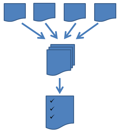
Write down the info for the different areas you need to make modifications for. In the picture below you see what areas to cover:
Classes, Symbols, Properties, Tags and Annotations
Step 2: Create classes, properties and selection lists
Assets (Symbols and Lines)
The first thing you start with is adding additional classes for new symbols. Moving sub-classes from one class to another (e.g. the Sight Glass is now supposed to be under Hand Valves) is not possible. You have to remove the old class and create a new one under the new section.
Before you start creating properties – which contain essentially all the data for your Tags, Annotations, Lists and Reports – you have to think about where you create the properties.
In the picture below you see the main class structure of the P&ID section of the overall configuration.
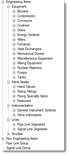
A property created for a class will be available for all sub-classes of that class. So creating a property for Engineering Items is available for Equipment, Inline Assets, Instrumentation, Lines and Nozzles.
If you need a property be available for equipment only, then you create it for the Equipment class.
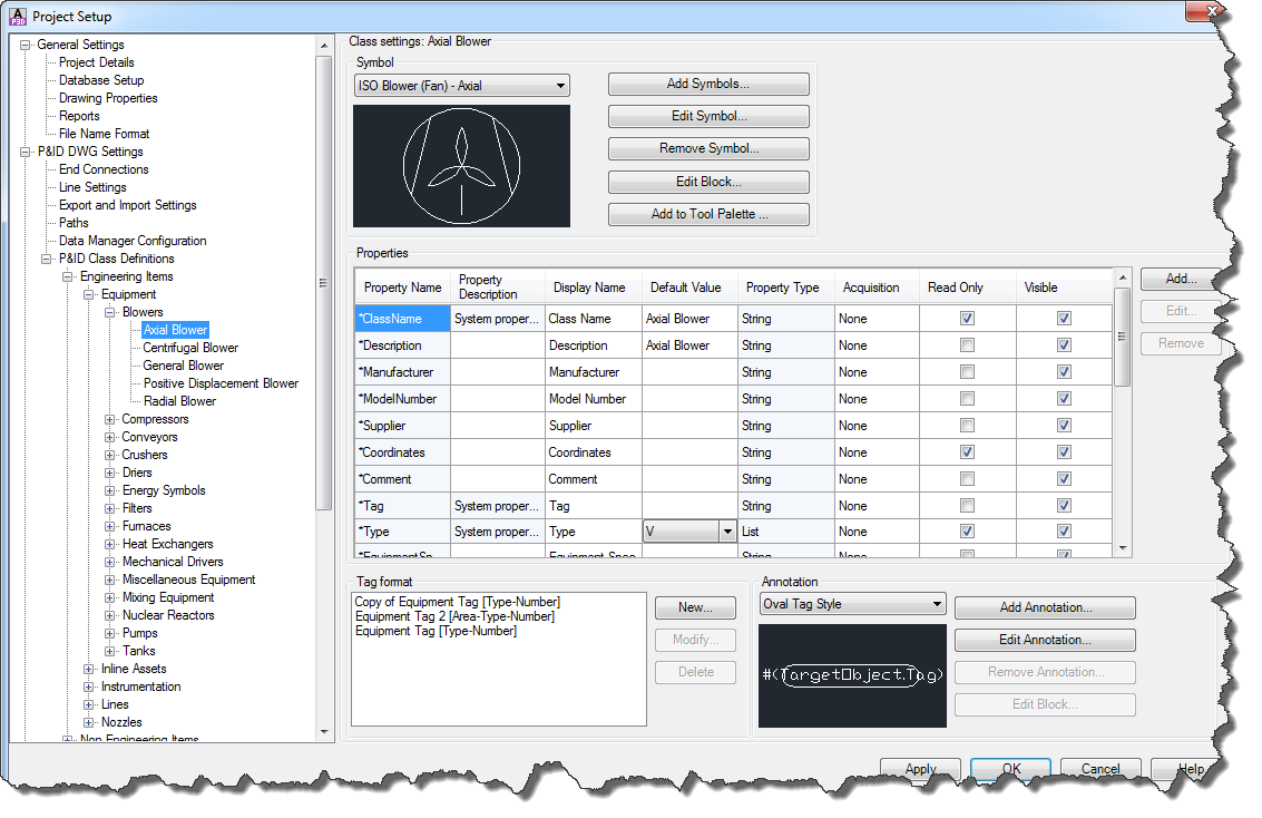
When you select Equipment class you recognize a * in front of the first six properties. This indicates that these properties are from a class above (and maybe even further up the tree).
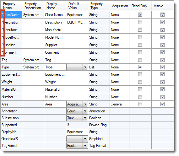
The order of properties can’t be changed.
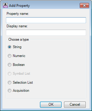
New properties will be added at the end. The property name can’t be changed either, but the Display name can. The property type can’t be changed as well. If name or type has to be changed you need to delete the property and create it again.