

Improved life cycle
small, compact camera packages
excellent sensitivity
less vulnerable to EMI (Electromagnetic Interference) and
RFI (Radio Frequency Interference)
cost effective
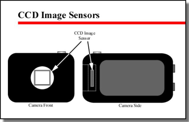
A CCD image sensor is actually an integrated circuit (IC).
One surface of the integrated circuit — the sensor face
plate — forms an array of light-sensitive devices (pixels).
Light striking this array causes electrons to flow in
proportion to the amount of light exciting a specific pixel.
Note that this explanation has been simplified. In reality, the
actual process is more complicated, with several variations
depending on the specific CCD technology in use. The
most common CCD technologies in CCTV applications
include:
MOS
Interline transfer
Frame transfer
Cameras incorporating MOS — Metal Oxide Semiconductor
— technology are currently at the low end of sensitivity and
resolution for CCTV applications. These cameras function
most satisfactorily in bright, even lighting. Shadows cause
problems for MOS cameras, with significant loss of detail in
the darker areas. In addition, MOS technology has a high
resistance to infrared wavelengths, further limiting the camera's ability to produce sharp, crisp images. Interline transfer CCD cameras utilize Improved Metal Oxide Semiconductors. The pixels on the image are arranged in rows and columns, each separated by small spaces. The CCD uses this space to transfer the charge from the actual sensing pixel to a storage area. Unlike the low end MOS cameras, interline transfer cameras have some infrared sensitivity which can be increased by adding filters. The characteristics of an interline transfer CCD camera allow a particular camera to be set up for use either in daylight or at night, but the same camera cannot be used for both.
Frame transfer CCD's — unlike interline transfer CCD's —have no spaces between the pixels on the image sensor.
Therefore, the actual surface area of each pixel is larger, resulting in a larger overall image area. The charges created as light strikes the pixels are moved to a storage area in the CCD one complete "frame" at a time. Frame
Transfer CCD's produce high-quality images. They are good in low light and have better IR sensitivity than either MOS or interline transfer CCD's. Color rendition, particularly in daylight, is excellent. Not surprisingly, of the three CCD types discussed here, cameras utilizing Frame Transfer technology generally have a higher cost.
Resolution
General Camera Specifications for CCTV Applications
When selecting a camera, system designers must consider a number of factors that affect the quality of the image and system reliability. These
factors fall into seven general categories: image sensor resolution
signal-to-noise ratio automatic light compensation synchronization
signal output environmental conditions and camera reliability dimensions and weight . We will look briefly at each of these issues. As we do so, keep in mind that better cameras (with higher resolution, sensitivity, and signal-tonoise ratios) typically cost more, and cost is also a factor to consider is systems design.
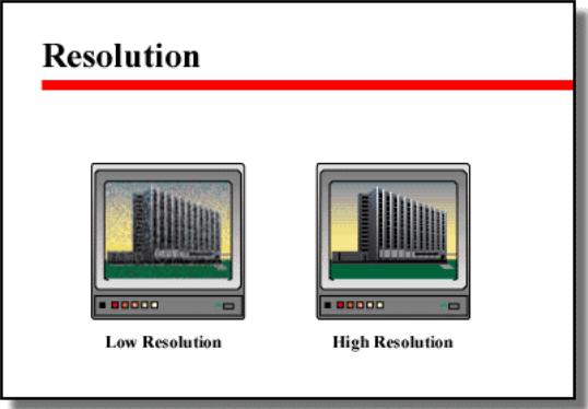
Resolution
Resolution is expressed as the number of lines scanned by the image sensor and output from the camera. As suggested in the figure,
resolution varies from camera to camera. In general, for CCTV applications, image sensor resolution should be at least 600 lines. Cameras with lower resolution (home video cameras often report a resolution of Cameras 450 lines) may not provide the detail necessary for detection, recognition or identification. On the other hand, high resolution cameras (up to 800 lines or more) may not be necessary except in highly specialized applications.
Signal-to-Noise Ratio
All camera specifications should list a signal-to-noise (S/N) ratio for the
camera. Simply stated, signal-tonoise ratio is the amount "visual noise" present in a video signal in comparison to the "pure" image information in the same signal. Noise — in the form of "snow" — can often be seen on a monitor especially when a camera is transmitting black (because it is in total darkness, the iris is completely closed, or the lens cap is on). All cameras produce noise. Better cameras have higher signal-to-noise ratios. A S/N ratio is expressed in decibels. Mathematically, it is the ratio of the peak signal value compared to the peak value of electromagnetic interference (EMI). The greater the ratio (number of decibels) the "cleaner" and better defined the picture. Any value over 40 dB is acceptable.
Keep in mind that signal to noise ratios should be linked with camera
sensitivity. A camera with high sensitivity and 40 dB signal-to-noise
will produce a better image than a camera with low sensitivity and 40 dB
S/N. In addition, some cameras have "gain" circuitry which allows the
camera to produce pictures in lower light, but gain control can introduce
significant levels of noise. Automatic Gain Control senses the signal
dropping below full video levels. When this occurs the amplifier
activates and compensates for the drop, maintaining the signal above
full vide levels at its designated range.