

Laboratory work #3
Investigation of remote-indicating electrical
AVIATION TACHOMETERS
Work objectives: learn the principle of operation, structure, properties and exploitation features of remote-indicating electrical aviation tachometers, get the basic technical characteristics, analyze influencing factors, clarify the reasons of errors and find out, how to decrease its amount.
Main task
Learn the principle of operation and structure of tachometer and laboratory plant.
Verify one measurement channel of tachometer (pickup - one indicator) and draw graphs that indicate an absolute error and variation dependency on its readings.
Verify pickup - two indicators channel draw graphs that indicate an absolute error and variation dependency on its readings.
Clarify the dependencies of tachometer readings, frequency values, linear voltages, current used by one measurement channel on pickup shaft rotation frequency. Draw graphs of gotten dependencies and calculate apparent pickup power.
Discover the influence of wires resistance changes on tachometer readings.
The basic theoretical information
One of the basic parameters, which permit to determine engine traction, is aviation engine shaft rotation frequency. Tachometers are the devices, used to measure this parameter.
Drag-type
(eddy current) electrical tachometers become widely used because of
their simplicity and reliability. The measurement range of rotation
frequency of these devices is rather wide: 4,00 – 4000 revolutions
per minute (rpm) of reciprocator and 1000 – 20000 rpm of turboprop
engine. There is dependence between the number of revolutions per
minute (rpm) n
and shaft rotation frequency (angular rotation velocity)
![]() (radians per second):
(radians per second):
![]() ,
,
where
![]() ,
(F – frequency in Hz).
,
(F – frequency in Hz).

Fig.1.:1 – gauge of tachometer, 2 – stator winding, 3 - hysteresis discs, 4 – 2 cross-formed constant magnets, 5 - embedded constant magnets, 6 – thermomagnetic shunt, 7 - moveable conducted disc, 8 – spring, 9 – damping disc, 10 - damping magnets, 11 – pointer.
Like
any other measurement device, tachometer consists of three basic
components: gauge (fig.1, 1
and
fig.2),
converter of the gauge output signal and indicating device. Gauge is
used to convert shaft rotation frequency
into electric signal
![]() ,
which frequency is linearly connected with
(the number of revolutions n).
,
which frequency is linearly connected with
(the number of revolutions n).
Tachometer gauge (fig.2) is a synchronous AC-generator with variable frequency. Rotor of the gauge is a bipolar or fourpolar magnet, connected with an aviation engine drive shaft by tang 1 – a long thin roller, inserted in an empty bush 3.
G enerator
rotor is rotating inside stator coils 5, placed into twelve slots of
set 9, made from transformer iron plates. Plates with winding are
inside the case, which consists of back 6 and front 8 halves, tided
up with screw-bolts 7. On the front half of the case 8 there is a
coupling nut 10 – a binding of a generator to an aviation engine.
enerator
rotor is rotating inside stator coils 5, placed into twelve slots of
set 9, made from transformer iron plates. Plates with winding are
inside the case, which consists of back 6 and front 8 halves, tided
up with screw-bolts 7. On the front half of the case 8 there is a
coupling nut 10 – a binding of a generator to an aviation engine.
G
Fig.2.
1 – tang, 2 – rotor, 3 - empty bush, 4 – bearing, 5 – stator
coils, 6 – back part of the case, 7 – screw-bolt, 8 – front
part of the case, 9 – set of iron plates
T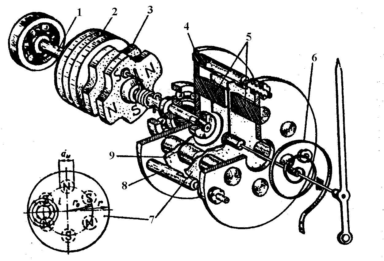 he
rotating magnetic field, excited in the synchronous engine stator
windings, magnetize hysteresis discs (made of ferromagnetic alloy
with large coercive force). Magnetic field of the discs follows poles
of the rotating magnetic field, but due to large hysteresis in the
material poles of the discs remain behind poles of the stator field
to certain angle. As a result, the moment of rotation appears which
rotates rotor of the synchronous engine.
he
rotating magnetic field, excited in the synchronous engine stator
windings, magnetize hysteresis discs (made of ferromagnetic alloy
with large coercive force). Magnetic field of the discs follows poles
of the rotating magnetic field, but due to large hysteresis in the
material poles of the discs remain behind poles of the stator field
to certain angle. As a result, the moment of rotation appears which
rotates rotor of the synchronous engine.
I
Fig.3.:
1 – shaft, 2 – hysteresis discs, 3 – magnets, 4 – two
connected discs, 5 – constant magnets, 6 – spring, 7 – movable
conducted disc, 8 - screw, 9 –thermomagnetic shunt .
If some sudden change in rotation frequency of the engine shaft happens, then rotor of the synchronous engine can break the synchronous rotation. In this case hysteresis discs help moving system to lock in synchronism again.
A sensitive element of tachometer consists of two connected discs 4 (fig.3) with embedded constant magnets (fig. 1, 5 and fig.3, 5) and thermomagnetic shunt (fig. 1, 6 and fig.3, 9) on them. Also there is a moveable conducted disc 7 (fig.3) in a magnetic field of the magnets 5. Discs 4 are situated on the same axis with engine rotor and disc 7 is mounted at the axis of the indicator pointers. Damper disc and one end of counteractive spring are strengthened to this axis.
During the rotation of discs 4 (fig.3) with magnets 5, the eddy currents appear inside the disc 7, creating their electromagnetic field. As a result of interaction between the cores magnetic fields and eddy currents, the moment appears, trying to rotate the disc 7 to the direction of tachometric unit rotation. Spiral spring 6 prevents this rotation.
To decrease dynamic errors during the transient processes, the second eddy current unit is used as a damper. Disc 9 (fig.1) is placed on the axis of pointer 11 and the disc with damping magnets 10 is mounted rigidly to device’s case. At significant oscillation of the rotation frequency in moving system eddy currents appear in the damping disc. These currents interact with magnetic field of constant magnets 10, leading to damping of oscillations in moveable indicator system with pointer.
Kinematics of dual indicator with sensitive elements is shown on fig.4.
F ig.4.
Kinematics of the dual indicator:
ig.4.
Kinematics of the dual indicator: