Lesson 2
1. Translate the text. Use a dictionary.
Microwave transmission lines
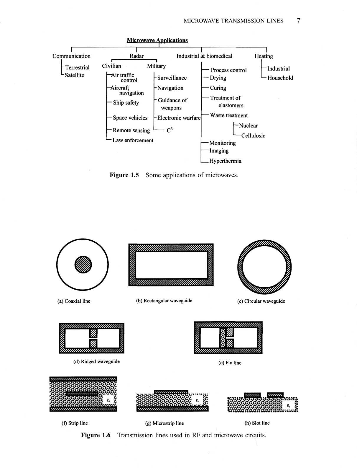
Figure 1.6 shows selected transmission lines used in RF and microwave circuits. The most common transmission line used in the RF and microwave range is the coaxial line. A low-loss dielectric material is used in these transmission lines to minimize the signal loss. Semirigid coaxial lines with continuous cylindrical conductors outside perform well in microwave range. In order to ensure single-mode transmission, the cross-section of a coaxial line must be much smaller in comparison with the signal wavelength. However, this limits the power capacity of these lines. In high-power microwave circuits, waveguides are used in place of coaxial lines. Rectangular waveguides are commonly employed for connecting the high-power microwave devices because these are easy to manufacture in comparison with circular waveguides. However, certain devices (such as rotary joints) require a circular cross-section. The ridged waveguide provides broadband operation in comparison with the rectangular one. The fin line shown in Figure 1.6 (e) is commonly used in the mm-wave band. Physically, it resembles a combination of slot line enclosed in a rectangular waveguide.
The transmission lines illustrated in Figure 1.6 (f)-(h) are most convenient in connecting the circuit components on a printed circuit board (PCB). The physical dimensions of these transmission lines are dependent on the dielectric constant er of insulating material and on the operating frequency band. The characteristics and design formulas of selected transmission lines are given in the appendices. Chapter 2 provides an overview of wireless communication systems and their characteristics.
Lesson 3
1. Translate the text. Use a dictionary
Terrestrial communication
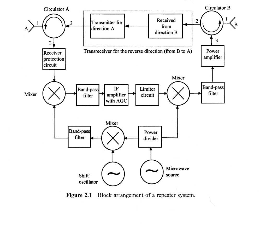
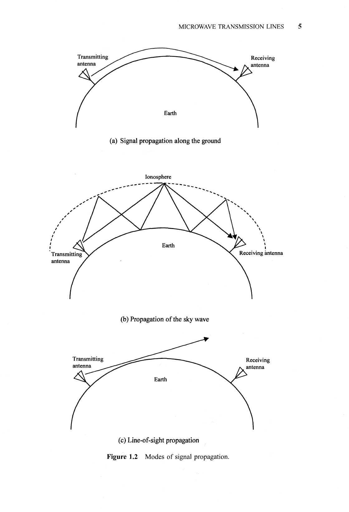
As mentioned in the preceding chapter, microwave signals propagate along the line-of-sight. Therefore, the earth-curvature limits the range over which a microwave communication link can be established. A transmitting antenna sitting on a 25-foot-high tower can typically communicate only up to a distance of about 50 km. The repeaters can be placed at regular intervals to extend the range. Figure 2.1 illustrates the block diagram of a typical repeater. The repeater system operates as follows. A microwave signal arriving at antenna A works as input to port 1 of the circulator. It is directed to port 2 without loss, assuming that the circulator is ideal. Then it passes through the receiver protection circuit that limits the magnitude of large signals but passes those of low intensity with negligible attenuation. The purpose of this circuit is to block excessively large signals from reaching the receiver input. The mixer following it works as a down-converter that transforms a high-frequency signal to a low frequency one, typically in the range of 70 MHz. The Schottky diode is generally employed in the mixer because of its superior noise characteristics. This frequency conversion facilitates amplification of the signal economically. A band-pass filter is used at the output of the mixer to stop undesired harmonics. An intermediate frequency (IF) amplifier is then used to amplify the signal. It is generally a low-noise solid-state amplifier with ultralinear characteristics over a broadband. The amplified signal is mixed again with another signal for up-conversion of frequency. After filtering out undesired harmonics introduced by the mixer it is fed to a power amplifier stage that feeds circulator В for onward transmission through antenna B. This up-converting mixer circuit generally employs the varactor diode. Circulator В directs the signal entering at port 3 to the antenna connected at its port 1. Similarly, the signal propagating upstream is received by antenna В and the circulator directs it toward port 2. It then goes through the processing as described for the downstream signal and is radiated by antenna A for onward transmission. Hence, the downstream signal is received by antenna A and transmitted in the forward direction by antenna B. Similarly, the upstream signal is received by antenna В and forwarded to the next station by antenna A. The two circulators help channel the signal in the correct direction.
A parabolic antenna with tapered horn as primary feeder is generally used in microwave links. This kind of composite antenna system, known as the hog-horn, is fairly common in high-density links because of its broadband characteristics. These microwave links operate in the frequency range of 4-6 GHz, and signals propagating in two directions are separated by a few hundred megahertz. Since this frequency range overlaps with the C-band satellite communication, their interference needs to be taken into design consideration. A single frequency can be used twice for transmission of information using vertical and horizontal polarization