

CCNP 642-811 BCMSN Exam Certification Guide - Cisco press
.pdf16 Chapter 1: Campus Network Overview
Figure 1-2 Segmentation Using VLANs
VLAN 1: 192.168.1.0
|
|
|
|
|
|
|
|
|
|
|
|
|
|
|
|
|
|
|
|
|
|
|
|
|
|
|
|
|
|
|
|
|
|
|
|
|
|
|
|
|
|
|
|
|
|
|
|
|
|
|
|
|
|
|
|
|
|
|
|
|
|
|
|
|
|
|
|
|
|
|
|
|
|
|
|
|
|
|
|
|
|
|
|
|
|
|
|
|
|
|
|
|
|
|
|
|
|
|
|
|
|
|
|
|
|
|
|
|
|
|
|
|
|
|
|
|
|
|
|
|
|
|
|
|
|
|
|
|
|
|
|
|
|
|
|
|
|
|
|
|
|
|
|
|
|
|
|
|
|
|
|
|
|
|
|
|
|
|
|
|
|
|
|
|
|
|
|
|
|
|
|
|
|
|
|
|
|
|
|
|
|
|
|
|
|
|
|
|
|
|
|
|
|
|
|
|
|
|
|
|
|
|
|
|
|
|
|
|
|
|
|
|
|
|
|
|
|
|
|
|
|
|
|
|
|
|
|
|
|
|
|
|
|
|
|
|
|
|
|
|
|
|
|
|
|
|
|
|
|
|
|
|
|
|
|
|
|
|
|
|
|
|
|
|
|
|
|
|
|
|
|
|
|
|
|
|
|
|
|
|
|
|
|
|
|
|
|
|
|
|
|
|
|
|
|
|
|
|
|
|
|
|
|
|
|
|
|
|
|
|
|
|
|
|
|
|
|
|
|
|
|
|
|
|
|
|
|
|
|
|
|
|
|
|
|
|
|
|
|
|
|
|
|
|
|
|
|
|
|
|
|
|
|
|
|
|
|
|
|
|
|
|
|
|
|
|
|
|
|
|
|
|
|
|
|
|
|
|
|
|
|
|
|
|
|
|
|
|
|
|
|
|
|
|
|
|
|
|
|
|
|
|
|
|
|
|
|
|
|
|
|
|
|
|
|
|
|
|
|
|
|
|
|
|
|
|
|
|
|
|
|
|
|
|
|
|
|
|
|
|
|
|
|
|
|
|
|
|
|
|
|
|
|
|
|
|
|
|
|
|
|
|
|
|
|
|
|
|
|
|
|
|
|
|
|
|
|
|
|
|
|
|
|
|
|
|
|
|
|
|
|
|
|
|
|
|
|
|
|
|
|
|
|
|
|
|
|
|
|
|
|
|
|
|
|
|
|
|
|
|
|
|
|
|
|
|
|
|
|
|
|
|
|
|
|
|
|
|
|
|
|
|
|
|
|
|
|
|
|
|
|
|
|
|
|
|
|
|
|
|
|
|
|
|
|
|
|
|
|
|
|
|
|
|
|
|
|
|
|
|
|
|
|
|
|
|
|
|
|
|
|
|
|
|
|
|
|
|
|
|
|
|
|
|
|
|
|
|
|
|
|
|
|
|
|
|
|
|
|
|
|
|
|
|
|
|
|
|
|
|
|
|
|
|
|
|
|
|
|
|
|
|
|
|
|
|
|
|
|
|
|
|
|
|
|
|
|
|
|
|
|
|
|
|
|
|
|
|
|
|
|
|
|
|
|
|
|
|
|
|
|
|
|
|
|
|
|
|
|
|
|
|
|
|
|
|
|
|
|
|
|
|
|
|
|
|
|
|
|
|
|
|
|
|
|
|
|
|
|
|
|
|
VLAN 2: 192.168.2.0 |
|
|
|
|
|
|
|
|
|
|
|
|
|
|
VLAN 3: 192.168.3.0 |
|
||||||||||||||||||||||||||||
Figure 1-3 Routing Traffic with VLANs
|
|
|
VLAN 1: 192.168.1.0 |
|
|
|
|
|
|
VLAN 2: 192.168.2.0 |
|
||||||||||||||||||||||||||||
|
|
|
|
|
|
|
|
|
|
|
|
|
|
|
|
|
|
|
|
|
|
|
|
|
|
|
|
|
|
|
|
|
|
|
|
|
|
|
|
|
|
|
|
|
|
|
|
|
|
|
|
|
|
|
|
|
|
|
|
|
|
|
|
|
|
|
|
|
|
|
|
|
|
|
|
|
|
|
|
|
|
|
|
|
|
|
|
|
|
|
|
|
|
|
|
|
|
|
|
|
|
|
|
|
|
|
|
|
|
|
|
|
|
|
|
|
|
|
|
|
|
|
|
|
|
|
|
|
|
|
|
|
|
|
|
|
|
|
|
|
|
|
|
|
|
|
|
|
|
|
|
|
|
|
|
|
|
|
|
|
|
|
|
|
|
|
|
|
|
|
|
|
|
|
|
|
|
|
|
|
|
|
|
|
|
|
|
|
|
|
|
|
|
|
|
|
|
|
|
|
|
|
|
|
|
|
|
|
|
|
|
|
|
|
|
|
|
|
|
|
|
|
|
|
|
|
|
|
|
|
|
|
|
|
|
|
|
|
|
|
|
|
|
|
|
|
|
|
|
|
|
|
|
|
|
|
|
|
|
|
|
|
|
|
|
|
|
|
|
|
|
|
|
|
|
|
|
|
|
|
|
|
|
|
|
|
|
|
|
|
|
|
|
|
|
|
|
|
|
|
|
|
|
|
|
|
|
|
|
|
|
|
|
|
|
|
|
|
|
|
|
|
|
|
|
|
|
|
|
|
|
|
|
|
|
|
|
|
|
|
|
|
|
|
|
|
|
|
|
|
|
|
|
|
|
|
|
|
|
|
|
|
|
|
|
|
|
|
|
|
|
|
|
|
|
|
|
|
|
|
|
|
|
|
|
|
|
|
|
|
|
|
|
|
|
|
|
|
|
|
|
|
|
|
|
|
|
|
|
|
|
|
|
|
|
|
|
|
|
|
|
|
|
|
|
|
|
|
|
|
|
|
|
|
|
|
|
|
|
|
|
|
|
|
|
|
|
|
|
|
|
|
|
|
|
|
|
|
|
|
|
|
|
|
|
|
|
|
|
|
|
|
|
|
|
|
|
|
|
|
|
|
|
|
|
|
|
|
|
|
|
|
|
|
|
|
|
|
|
|
|
|
|
|
|
|
|
|
|
|
|
|
|
|
|
|
|
|
|
|
|
|
|
|
|
|
|
|
|
|
|
|
|
|
|
|
|
|
|
|
|
|
|
|
|
|
|
|
|
|
|
|
|
|
|
|
|
|
|
|
|
|
|
|
|
|
|
|
|
|
|
|
|
|
|
|
|
|
|
|
|
|
|
|
|
|
|
|
|
|
|
|
|
|
|
|
|
|
|
|
|
|
|
|
|
|
|
|
|
|
|
|
|
|
|
|
|
|
|
|
|
|
|
|
|
|
|
|
|
|
|
|
|
|
|
|
|
|
|
|
|
|
|
|
|
|
|
|
|
|
|
|
|
|
|
|
|
|
|
|
|
|
|
|
|
|
|
|
|
|
|
|
|
|
|
|
|
|
|
|
|
|
|
|
|
|
|
|
|
|
|
|
|
|
|
|
|
|
|
|
|
|
|
|
|
|
|
|
|
|
|
|
|
|
|
|
|
|
|
VLAN 3: 192.168.3.0 |
VLAN 4: 192.168.4.0 |
Campus Network Models 17
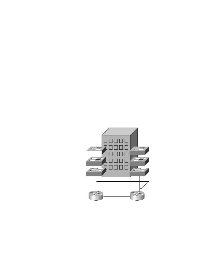
Ports on each switch have been grouped and assigned to one VLAN. A port from each VLAN then connects to the router. The router then forwards packets between VLANs through these ports.
To gain the most benefit from routed approaches and VLAN approaches, most campus networks are now built with a combination of Layer 2 switches and routers, or with multilayer switches. Again, the Layer 2 switches are generally placed where the small broadcast domains are located, linked by routers (or multilayer switches) that provide Layer 3 functionality. In this manner, broadcast traffic can be controlled or limited. Users can also be organized and given access to common workgroups, and traffic between workgroups can be interconnected and secured.
Figure 1-4 illustrates the structure of a typical routed and switched campus network. Here, the concept of Layer 2 switches and routers has been extended a bit. Each switch in the buildings supports three different VLANs for its users. A single switch port from each connects back to a router. Any switch port can normally carry only one VLAN, so something special must be occurring. These ports have been configured as trunk links, carrying multiple VLANs. (Trunking is discussed in Chapter 6, “VLANs and Trunks.”)
Figure 1-4 Typical Campus Network Structure
|
|
VLANS 1/2/3 |
|
|
|
|
|
|
|
|
|
VLANS 4/5/6 |
|||||
|
|
|
|
|
|
|
|
|
|
|
|||||||
|
|
|
|
|
|
|
|
|
|
|
|
|
|
|
|
|
|
|
|
|
|
|
|
|
|
|
|
|
|
|
|
|
|
|
|
|
|
|
|
|
|
|
|
|
|
|
|
|
|
|
|
|
|
|
|
|
|
|
|
|
|
|
|
|
|
|
|
|
|
|
|
|
|
|
|
|
|
|
|
|
|
|
|
|
|
|
|
|
|
|
|
|
|
|
|
|
|
|
|
|
|
|
|
|
|
|
|
|
|
|
|
|
|
|
|
|
|
|
|
|
|
|
|
|
|
|
|
|
|
|
|
|
|
|
|
|
|
|
|
|
|
|
|
Trunk Links
Network Traffic Models
To design and build a successful campus network, you must gain a thorough understanding of the traffic generated by applications in use, plus the traffic flow to and from the user communities. All devices on the network will produce data to be transported across the network. Each device can involve many applications that generate data with differing patterns and loads.

18 Chapter 1: Campus Network Overview
Applications, such as e-mail, word processing, printing, file transfer, and most web browsers, bring about data traffic patterns that are predictable from source to destination. However, newer applications, such as videoconferencing, TV or video broadcasts, and IP telephony, have a more dynamic user base, which makes traffic patterns difficult to predict or model.
Traditionally, users with similar applications or needs have been placed in common workgroups, along with the servers they access most often. Whether these workgroups are logical (VLAN) or physical networks, the idea is to keep the majority of traffic between clients and servers limited to the local network segment. In the case of the switched LANs connected by routers mentioned earlier, both clients and servers would be connected to a Layer 2 switch in the workgroup’s proximity. This connection provides good performance while minimizing the traffic load on the routed network backbone.
This concept of network traffic patterns is known as the 80/20 rule. In a properly designed campus network, 80 percent of the traffic on a given network segment is local (switched). No more than 20 percent of the traffic is expected to move across the network backbone (routed).
If the backbone becomes congested, the network administrator will realize that the 80/20 rule is no longer being met. What recourses are available to improve network performance again? Because of expense and complexity, upgrading the campus backbone is not a desirable option. The idea behind the 80/20 rule is to keep traffic off the backbone. Instead, the administrator can implement the following solutions:
■Reassign existing resources to bring the users and servers closer together.
■Move applications and files to a different server to stay within a workgroup.
■Move users logically (assigned to new VLANs) or physically to stay near their workgroups.
■Add more servers, which can bring resources closer to the respective workgroups.
Needless to say, conforming modern campus networks to the 80/20 rule has become difficult for the network administrator. Newer applications still use the client/server model, but server portions have been centralized in most enterprises. For example, databases, Internet and intranet technologies, and e-mail are all available from centralized servers. Not only do these applications involve larger amounts of data, but they also require a greater percentage of traffic to cross a network backbone to reach common destinations—quite a departure from the 80/20 rule.
This new model of campus traffic has become known as the 20/80 rule. Now, only 20 percent of the traffic is local to the workgroup, while at least 80 percent of the traffic is expected to travel off the local network and across the backbone.
This shift in traffic patterns puts a greater burden on the campus backbone’s Layer 3 technology. Now, because traffic from anywhere on the network can be destined for any other part of the

Hierarchical Network Design 19
network, the Layer 3 performance ideally should match the Layer 2 performance. Generally, Layer 3 forwarding involves more processing resources because the data packets must be examined in greater depth. This added computation load can create bottlenecks in the campus network, unless carefully designed.
Likewise, a campus network with many VLANs can become difficult to manage. In the past, VLANs were used to logically contain common workgroups and common traffic. With the 20/80 rule, end devices need to communicate with many other VLANs. Measuring traffic patterns and redesigning the campus network become too cumbersome just to keep up with the 20/80 rule model.
Predictable Network Model
Ideally, you should design a network with a predictable behavior in mind to offer low maintenance and high availability. For example, a campus network needs to recover from failures and topology changes quickly and in a predetermined manner. You should scale the network to easily support future expansions and upgrades. With a wide variety of multiprotocol and multicast traffic, the network should be able to support the 20/80 rule from a traffic standpoint. In other words, design the network around traffic flows instead of a particular type of traffic.
Traffic flows in a campus network can be classified as three types, based on where the network service is located in relation to the end user. Table 1-3 lists these types, along with the extent of the campus network that is crossed.
Table 1-3 Types of Network Services
Service Type |
Location of Service |
Extent of Traffic Flow |
|
|
|
Local |
Same segment/VLAN as user |
Access layer only |
|
|
|
Remote |
Different segment/VLAN as user |
Access to distribution layers |
|
|
|
Enterprise |
Central to all campus users |
Access to distribution to core layers |
|
|
|
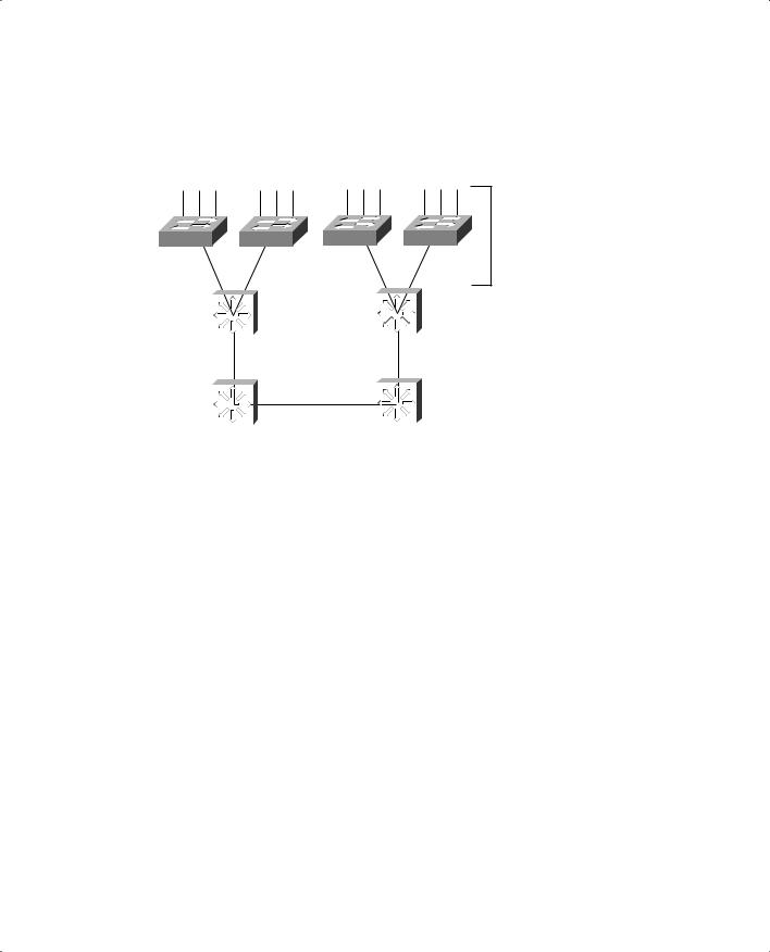
The terms access layer, distribution layer, and core layer are each distinct components of the hierarchical network design model. The network is divided into logical levels, or layers, according to function. These terms and the hierarchical network design are discussed in the next section.
Hierarchical Network Design
You can structure the campus network so that each of the three types of traffic flows or services outlined in Table 1-3 are best supported. Cisco has refined a hierarchical approach to network design that enables network designers to logically create a network by defining and using layers of devices. The resulting network is efficient, intelligent, scalable, and easily managed.
20 Chapter 1: Campus Network Overview
The hierarchical model breaks a campus network down into three distinct layers, as illustrated in Figure 1-5.
Figure 1-5 Hierarchical Network Design
Access
Layer
|
|
|
|
|
|
|
|
Si |
|
|
|
Si |
|
|
|
Distribution |
|
|
|
|
|
|
|
|
|
|
|
|
Layer |
|
|
|
|||
|
|
|
|
|
Core |
|
|
|
|
|
|
|
|
|
|
|
|
|
|
|
|
|
|
Si |
|
Si |
|
|
Layer |
|
|
|
|
|
|
These layers are the access layer, distribution layer, and core layer. Each layer has attributes that provide both physical and logical network functions at the appropriate point in the campus network. Understanding each layer and its functions or limitations is important to properly apply the layer in the design process.
Access Layer
The access layer is present where the end users are connected to the network. Devices in this layer, sometimes called building access switches, should have the following capabilities:
■Low cost per switch port
■High port density
■Scalable uplinks to higher layers
■User access functions such as VLAN membership, traffic and protocol filtering, and QoS
■Resiliency through multiple uplinks

Cisco Products in the Hierarchical Design 21
Distribution Layer
The distribution layer provides interconnection between the campus network’s access and core layers. Devices in this layer, sometimes called building distribution switches, should have the following capabilities:
■High Layer 3 throughput for packet handling
■Security and policy-based connectivity functions through access lists or packet filters
■QoS features
■Scalable and resilient high-speed links to the core and access layers
Core Layer
A campus network’s core layer provides connectivity of all distribution layer devices. The core, sometimes referred to as the backbone, must be capable of switching traffic as efficiently as possible. Core devices, sometimes called campus backbone switches, should have the following attributes:
■Very high throughput at Layer 2 or Layer 3
■No costly or unnecessary packet manipulations (access lists, packet filtering)
■Redundancy and resilience for high availability
■Advanced QoS functions
Cisco Products in the Hierarchical Design
Before delving into the design practices needed to build a hierarchical campus network, you should have some idea of the actual devices that you can place at each layer. Cisco has switching products tailored for layer functionality, as well as the size of the campus network.
For the purposes of this discussion, a large campus can be considered to span across several or many buildings in a single location. A medium campus might make use of one or several buildings, whereas a small campus might have only a single building.
Choose your Cisco products based on the functionality that is expected at each layer of a small, medium, or large campus. The products available at press time are described in the sections that follow and are summarized in table form for comparison. Don’t get lost in the details of the tables. Rather, try to understand which switch fits into which layer for a given network size.
NOTE Although Cisco offers a wide range of LAN switching products, several different operating systems and user interfaces are supported on different switch models. For the purposes of this book and the CCNP BCMSN exam, you should only be concerned with switches that run the Cisco IOS Software. Only these switches are listed in the tables that follow.

22 Chapter 1: Campus Network Overview
Although campus network design is presented as a three-layer approach (access, distribution, and core layers), the hierarchy can be collapsed or simplified in certain cases. For example, small or medium-sized campus networks might not have the size, multilayer switching, or volume requirements that would require the functions of all three layers. Here, you could combine the distribution and core layers for simplicity and cost savings. In this case, choose switch products based on the distribution layer features and access layer aggregation port densities needed.
Access Layer Switches
Recall that access layer devices should have these features:
■High port density to connect to end users
■Low cost
■Multiple uplinks to higher layers of the campus network
■Layer 2 services (traffic filtering, VLAN membership, and basic QoS)
Small or medium campus networks can use the Catalyst 2950 or 3550 (standard multilayer software image, SMI) series switches as access layer devices. These switches are useful to provide access to groups of less than 50 users and servers. Both switch families offer high-performance backplanes for efficient switching, and Fast or Gigabit Ethernet uplinks to distribution layer switches. These switches are also stackable, using Gigabit Ethernet links as a shared bus or as daisy-chained links to add port density in an access layer wiring closet. These switch families also offer a rich feature set, including QoS and switch clustering for improved performance and management.
For large campuses, the Catalyst 4000/4500 series switches provide advanced enterprise access layer functions. These switches can connect groups of less than 250 users and servers (10/100/ 1000BASE-T), or up to 92 dedicated Gigabit Ethernet devices. Greater Layer 2 functionality is provided as security, multicast support, and advanced QoS. The Catalyst 6500 can also be used for even higher user or server port densities in a large campus environment. For example, the Catalyst 6513 can support up to 576 FastEthernet ports.
NOTE On the Catalyst 4000/4500, only Supervisor III and IV support Cisco IOS Software. Be aware that other Supervisor modules run the Catalyst OS (also known as XDI, CatOS, or COS), but those are not dealt with here or in the exam.

Cisco Products in the Hierarchical Design 23
Table 1-4 lists each Catalyst switch family suitable for the access layer, along with the maximum port densities and backplane speeds.
Table 1-4 Catalyst Switches for the Access Layer
Catalyst |
|
|
|
Other |
Model |
Max Port Density |
Uplinks |
Max Backplane |
Features |
|
|
|
|
|
2950 |
12, 24, or 48 10/100 |
2 100FX or |
13.6 Gbps |
QoS, security |
|
|
1000BASE-X |
|
|
|
|
|
|
|
3550 (SMI) |
24 or 48 10/100 or |
2 1000BASE-X |
24 Gbps (12-port), |
Advanced |
|
12 10/100/1000BASE-T |
|
13.6 Gbps (48-port), |
QoS, security, |
|
|
|
or 8.8 Gbps (24-port) |
redundant |
|
|
|
|
power, inline |
|
|
|
|
power (24-port |
|
|
|
|
only) |
|
|
|
|
|
4000/4500 |
240 10/100 or 10/100/ |
100 or |
64 Gbps |
Advanced |
(Sup III or IV) |
1000BASE-T |
1000BASE-X |
|
QoS, security, |
|
|
|
|
redundant |
|
|
|
|
power, inline |
|
|
|
|
power |
|
|
|
|
|
Distribution Layer Switches
Switches used in the distribution layer should offer these features:
■Aggregation of access layer devices
■High Layer 3 multilayer switching throughput
■QoS support
■Port density of high-speed links to both the core and access layer switches
■Efficient support for redundant links and resiliency
In the distribution layer, uplinks from all access layer devices are aggregated, or come together. The distribution layer switches must be capable of processing the total volume of traffic from all the connected devices. These switches should have a port density of high-speed links to support the collection of access layer switches.
VLANs and broadcast domains converge at the distribution layer, requiring routing, filtering, and security. The switches at this layer must be capable of performing multilayer switching with high throughput. Only certain Catalyst switch models can provide multilayer switching; be sure to understand which ones can do this. (Chapter 13, “Multilayer Switching,” covers this topic in greater detail.)

24 Chapter 1: Campus Network Overview
The Catalyst 3550-12G or 3550-12T can serve as a distribution layer switch for up to 10 1000BASE-X and 2 10/100/1000BASE-T or 2 1000BASE -X and 10 10/100/1000BASE-T access layer uplinks, respectively, as might be found in small to mid-sized networks. (The Catalyst 3550 must run the Enhanced Multilayer switching software image (EMI) to support Layer 3 routing protocols.
Based on port density and certain functionality, you can use many Catalyst switches in more than one layer of a campus network. For example, because the Catalyst 3550 can offer a fixed 24 or 48-port 10/100BASE-T configuration with two Gigabit Ethernet uplinks, you might want to use it in wiring closets or the access layer to connect workgroups or hubs. The Gigabit Ethernet uplinks would then be links to distribution layer switches. In some cases, multiple access layer 2950 or 3550 switches can uplink into another 3550 at the distribution layer.
For larger campus networks, the Catalyst 4000/4500 and 6500 families offer high densities of Fast and Gigabit Ethernet for the distribution layer. A fully populated Catalyst 4006, for example, can support up to 30 Gigabit Ethernet ports or 240 10/100/1000BASE-T Ethernet ports. The Supervisor III or IV module provides both Cisco IOS Software and high-performance multilayer switching.
The Catalyst 6500 family offers much higher performance and port density that larger distribution layers can use. For example, the Catalyst 6513 can support up to 194 Gigabit Ethernet ports or 576 10/100 Ethernet ports. Multilayer switching is performed using an integrated Multilayer Switch Feature Card (MSFC), providing a throughput of up to 210 million packets per second.
Table 1-5 in the section “Product Summary” provides information on Cisco distribution layer switch products based on campus size.
Core Layer Switches
Recall the features required in core layer switches:
■Very high multilayer switching throughput
■No unnecessary packet manipulations (access lists and packet filtering), unless performed at wire speed
■Redundancy and resiliency for high availability
■Advanced QoS functionality
Devices in a campus network’s core layer or backbone should be optimized for high-performance Layer 2 or Layer 3 switching. Because the core layer must handle large amounts of campus-wide data (due to the new 20/80 rule of traffic flow), the core layer should be designed with simplicity and efficiency in mind.

Cisco Products in the Hierarchical Design 25
Small campus networks can use the Catalyst 3550 or 4000 family in the core layer. These switches provide reasonable port densities of Fast and Gigabit Ethernet to aggregate access layer uplinks. If the distribution and core layers are combined, both of these switch families can support multilayer switching in hardware.
Medium-sized and large campus networks can use the Catalyst 6500 family. Again, high port densities of Gigabit Ethernet are possible. This family of switches has high-performance, scalable switching from 32 Gbps to 256 Gbps. With the new Supervisor Engine 720, the performance is even greater at 720 Gbps! Layer 3 security, powerful QoS, and complete routing protocol support are available with the combination of Supervisor and MSFC modules, as well as the native Cisco IOS Software.
Table 1-5 in the section, “Product Summary,” provides information on Cisco core layer switch products based on campus size.
Product Summary
As a quick review, see Table 1-5 for a summary of the various Catalyst switch families used for various applications. The table is broken down by campus network size and by campus network layer. The application of a particular switch in a network layer is a matter of choice and is not required. For example, if an access layer wiring closet in a small campus network has 200 users attached, choosing a single Catalyst 4000 might make more sense than several Catalyst 3550s. In this case, the size of the access layer workgroup dictates the choice of switch and port density more than the overall campus network size.
Table 1-5 Summary of Catalyst Switch Products and Typical Layer Applications
Campus Size |
Layer |
Catalyst Switch |
Key Features |
|
|
|
|
Any |
Access |
2950 |
< 50 users 10/100BASE-T; 100BaseFX or |
|
|
|
1000BASE-X uplinks |
|
|
|
|
|
|
3550 |
< 50 users 10/100BASE-T; 1000BASE-X |
|
|
|
uplinks |
|
|
|
|
|
|
4000/4500; |
< 250 users 10/100/1000BASE-T; 1000BASE- |
|
|
(Sup III or IV) |
X uplinks |
|
|
|
|
|
|
6500 |
> 250 users 10/100/1000Base-T; 1000Base-X |
|
|
|
uplinks |
|
|
|
|
continues