


Chapter 8
Designing the
Infrastructure
Solutions in this chapter:
■Design Considerations
■Site Considerations
■Designing with the Hierarchy in Mind
■Frame Relay Internetwork Design Considerations
■Capacity Planning for Your Infrastructure
■Protocol Planning Concerns
■Addressing Considerations
■Application and Network Services
■Application-Aware Networking
■Scalability Considerations
■Multimedia Services
■Planning for the Future Growth of Your Company’s Infrastructure
■High-Availability Design
;Summary
;Solutions Fast Track
;Frequently Asked Questions
415
416 Chapter 8 • Designing the Infrastructure
Introduction
You have decided that becoming an application service provider (ASP) is the right thing to do, so how do you go about setting it up? So far, the book has focused on the components of creating an ASP network infrastructure.This chapter will help you pull it all together.
In this chapter, we look at what it takes to design the infrastructure.This is what separates the network design and implementation engineers from the network administrators. If you design the network properly, there won’t be peals of joy and adulation. However, if you design your infrastructure poorly, your company will not be able to retain its current customers and attract new ones. Because many of you already have a viable network infrastructure, I wrote this chapter as a high-level overview of some of the considerations that you may face. I ask you to forgive any dated material; by the time this book is finished and sent to press, there is bound to be the next “latest and greatest” toy available on the market.
So, why do we do this? Designing the network is a thankless job, and it is probably one of the most difficult and most overlooked areas in networking; it is also essential to the success of your business. I think that most of us do this because we enjoy the challenge, the thrill and exhilaration that comes from solving the impossible…or because we like to play with toys. Even with all of the new toys, though, there is no such thing as a perfect network, but here is how you go about trying to achieve one.
Designing & Planning…
End-to-End Network Services for a Data Center Environment
Some of the challenges associated with creating an end-to-end ASP solution are protecting mission-critical programs and applications, creating security policies, being able to manage the environment, provide high availability, support for multimedia content (voice and video) and make the solution so that it scalable.
Always keep these issues in mind when applying for funding to build or expand your network. Remember that by addressing these concerns, you will add value to the company, so stress that whenever possible.
www.syngress.com

Designing the Infrastructure • Chapter 8 |
417 |
There is a great deal of detail with site preparation alone. In this chapter, there are some best practices on design and location of equipment.These are general guidelines and not a complete list, so if you are setting up a major data center, the designs in this chapter may not be large enough examples, as they are scaled to medium and large ASPs.This chapter mostly deals with Cisco Systems equipment and Microsoft Windows 2000 environments, but I do not mean to imply that these are the only vendors that you can use.
Design Considerations
There is no such thing as a perfect deployment of an ASP. Some things will make your company successful, and some will inhibit your growth. Remember that you should keep the following issues in mind in order to deploy a dynamic, interactive, application solution while providing access to various dissimilar clients.
Your infrastructure must address the following issues:
■It must provide an interoperable and distributed network environment that is compatible with Internet standards.
■Your application must not be location dependent.
■You must provide a framework that will incorporate disparate network data and application types from your clients and internal application developers.
■It must provide centralized management and security functions.
■It must be scaleable as usage grows.
Other items that you need to address in the implementation of a packetswitching infrastructure include:
■Hierarchical internetwork design
■Topology design
■Broadcast issues
■Performance issues
www.syngress.com

418 Chapter 8 • Designing the Infrastructure
NOTE
Part of this chapter focuses on general packet-switching considerations and Frame Relay internetworks. I selected Frame Relay because it presents a broad picture of design considerations for interconnection to packet-switching devices.
Getting Started: The Design Process
An internetwork requires many layers of thought and design that encompasses everything from physical space to future network considerations.There are generally three components when designing a large internetwork: data center networks, wide area networks (WAN), and remote users (in this case, your external clients).
■Data center networks are generally comprised of locally housed equip-
ment that will service your clients from a building, or set of buildings.
■Wide area networks are the connections between the data center and the customer.
■Remote users are your clients and telecommuter traffic that are subsets of your main clients.
Designing the network is a challenging task, but as I said earlier, you probably are doing this job because you like a challenge.You must take into account that each of the three components has its own distinct requirements. For example, an internetwork that is comprised of five meshed platforms can create all sorts of unpredictable problems, so attempting to create an even larger series of intermeshed networks that connect multiple customers who have their own network issues can be downright mind-boggling.
This is an age in which equipment is getting faster, sometimes by being more granular in the services that are offered, and other times, allowing more to be done within a single chassis. Infrastructure design is becoming more difficult due to ASPs moving toward more sophisticated environments that use multiple protocols, multiple media types, and allowing connections to domains outside your areas of influence because of customer requirements.
One of the greatest trade-offs in linking local area networks (LANs) and WANs into a packet-switching data network (PSDN) infrastructure is between
www.syngress.com

Designing the Infrastructure • Chapter 8 |
419 |
cost and performance.The ideal solution would optimize packet-based services, yet this optimization should not be interpreted to picking the mix of services that would represent the lowest possible tolls.Your customers are going to want speed, availability, and ease of use.To successfully implement a packet-service infrastructure, you should adhere to two basic rules:
■When designing and implementing a packet-switching solution, try to balance cost savings with your company’s internal performance requirements and promises to its customers.
■Try to build a manageable solution that can scale when more links and services are required by your company’s clientele.
Data Center,WAN, and Remote Links Defined
The data center is a building or set of buildings that house the infrastructure of your network. Most data centers consist of many platforms that are joined together to form the backbone.These centers usually use LAN technologies such as Fast Ethernet, Gigabit Ethernet, and Asynchronous Transfer Mode (ATM) to power their network.
The WAN is the way to connect your multiple customers and buildings across geographically dispersed areas.When you use WAN technologies (such as fiber, satellite, or copper) to connect your customers, you may have to pay for bandwidth from an external telecommunications provider.
Remote links (users) are those clients who work on a per-use agreement, or their internal resources use the applications from disparate areas, such as a home office, and need to access the network in various ways. Some of the more common ways are over the WAN through a virtual private network (VPN) connection and through remote access servers (RAS).
NOTE
There are several types of VPN solutions available. Depending on your needs and likes, multiple companies can provide clients for your type of network. Be sure to research whether these clients will support the types of traffic that will be running over these connections (for example AppleTalk, IPX/SPX, and in rare instances, SNA bridging). VPNs also allow for security by allowing encryption and authentication services.
www.syngress.com

420 Chapter 8 • Designing the Infrastructure
The Design Process—Getting Down to Business
Most design processes start with a good conceptual drawing, so let’s begin there— with a pencil and paper (or if you are more inclined,Visio or any other publishing software with which you are comfortable. I like crayons, but they don’t taste the same as the wrapper says they do) and some brainstorming.Try to start mapping out the proposed layout of the infrastructure.This is a multiple-step process, and these designs may never be fully finished, as they should be updated as the network grows and changes. Remember that one of the most important features of a network is scalability.
NOTE
A conceptual drawing is a reference tool that can later be used as documentation. It will help when you bring in other people to support your infrastructure, and will assist in the explanation of how and why your network functions the way it does. It will also help in future growth areas, as you can see any potential problems that may crop up. A map of your infrastructure will also help in the training of your network team, so you may not have to take that weekend call while you are on vacation when someone decides to “modify” or “streamline” the network. Being able to create a good conceptual drawing is a good skill to have for our highly competitive market. A well documented network should always have the most current and correct details, such as IP addresses. This is critical, not just a good idea.
The first step of this process is diagramming the “design” from the proverbial “30,000-foot” view. Depending on the situation, the first drawing should be just the physical locations and possible future locations of your buildings if designing a dispersed data center or WAN model.This will help you provision appropriate WAN connections, as well as future circuit provisions (Figure 8.1).
NOTE
Remember that provisioning bandwidth is an important issue and should be covered in detail. The design in Figure 8.1 may not be the most cost effective, but may be necessary due to network requirements. We discuss that later in this chapter.
www.syngress.com

Designing the Infrastructure • Chapter 8 |
421 |
Figure 8.1 The 30,000-Foot View
Seattle
Data Center
San Francisco
Data Center
Los Angeles
Data Center
|
Chicago |
|
Data Center |
|
Washington, D.C. |
OC-48 Link |
Data Center |
|
OC-48 Link |
OC-12 Link |
|
OC- |
|
|
|
12 |
Link |
|
Atlanta |
|
|
|
Data Center |
|
|
|
Link |
|
|
-12 |
|
OC-48 Link |
OC |
|
|
Dallas HQ |
|
||
|
|
|
|
Central Data Center
Site Considerations
Now that we have a conceptual drawing, we can delve into site considerations. This is might be an area over which you have very little control, yet it has a high impact on your design.The following sections provide the basis of how to implement your design, while considering physical limitations.
Physical Equipment Space
The next step in the design process should continue with an analysis of the physical space.The point here is that if there is insufficient space and/or resources (such as power, air-conditioning, etc.), there will be severe limitations on design and implementation.When you are building a new physical plant for your ASP, make sure that there is adequate space available and sufficient resources (power and cabling, as well as security) to suit your needs.
Here are some considerations for the physical plant implementation:
■When you can, scope out the physical layout of the room; there should be sufficient space to place the equipment to be installed.
■Find out whether the room is “fireproof ” with typical methods to contain a fire, and if the room is climate controlled.
■Find out how secure the room is (combination lock, keyed, keyless entry, retinal scan deoxyribonucleic acid (DNA) analysis, and so forth).
www.syngress.com

422Chapter 8 • Designing the Infrastructure
■Decide on what types of floor racks and/or cabinets for build-out purposes (19-inch network racks, 23-inch telecommunications racks).
■Make sure to pay attention to weight, power, and environment concerns.
■Weight This category will vary according to equipment and cabling.Try to scope out what type of equipment will go into each rack, and where it will be placed on the floor and within the rack itself. Depending on your wiring scheme, there may be an uneven distribution of weight, which may unbalance the racks you are installing. If at all possible, get the weight requirements from the vendor, and find a rack that is able to support what you are placing, plus approximately 20 percent of that weight for future equipment and swap out. In addition, take into account the flooring, and whether it can support the rack.
■Power This is usually an easy piece to scope out. Based on the vendor specifications for the equipment, you should ask the following questions. Does the room have a dedicated power source?
Does that source support the needs of the proposed equipment? Is there a backup power supply (uninterruptible power supply (UPS))? Does the room have a circuit breaker and a master shutoff switch? These are important questions for the present and future expand-
ability. Note that if there are any major questions, call an electrician.
■Environment This is always a little tricky, as this is the area with the most variance.You could write an entire book on this topic, but it probably would only be for civil engineers and architects. Some of the questions that you should ask when assessing the environment for the infrastructure include:
■How is the room secured?
■How are the climate control and ventilation handled (heat, ventilation, and air conditioning (HVAC))?
■ Is the room sealed, and is it set up for fire control?
■Does the flooring prevent static buildup?
■How is the cabling plant implemented?
■Should you use ladder racks or raised flooring?
www.syngress.com

Designing the Infrastructure • Chapter 8 |
423 |
Let us discuss the security issue first; as there is usually a high cost associated with the equipment installed, you will want the room theft-proof.The other issue to security is that you don’t want people to just come in and change the equipment or install things on a whim, so security is also able to provide restricted access to authorized personnel only.
Climate control topics can include many variables, such as temperature, humidity, and so forth.These factors are important; if the room is too hot, the equipment will not function properly if it overheats, and if it’s too cold, the possibility of freezing and cracking equipment exists. If the room is too humid, the equipment could short due to water in the equipment; if it is too dry, you run the risk of static electricity shorting the equipment. Recall that the equipment will emit its own heat, so even though the room may feel chilled while the equipment is off, once the equipment is running, the temperature will average out. Make sure to check the heat ratings of the equipment before designing your facility and rack layout.
Fireproofing is more straightforward. For a controlled room, the walls should go all the way to the roof to create an enclosed/sealed environment. A main reason for a sealed environment is a Halon dispensation system or other viable fire deterrent system that smothers the fire by displacing the oxygen in the room. (Technically, this can also be used for security, but I am not sure that killing someone is the way to go.)
Prevent static buildup by installing antistatic tile flooring. Under no circumstances should you use carpeting, as this will actually increase the static buildup that is natural with movement (and don’t wear corduroys; not only do they make bad fashion sense, they definitely add to your ability to create static). If you are building your infrastructure from scratch, you may want to consider installing raised flooring, as this will also help with cable management.
For cable plant implementation and management, you will want to hire a company that can install and certify their work with a registered communication distribution designer (RCDD).This will make insuring the room and equipment somewhat easier. In addition, they can usually come up with a best practice for you and your location.
www.syngress.com

424 Chapter 8 • Designing the Infrastructure
Configuring & Implementing…
General Rules for the Care and Feeding of Networks
■Weight This is pretty self-explanatory; if the equipment weighs more than the rack can support, then your equipment will fall down, go boom.
■Power Without sufficient power, all you have is an expensive paperweight.
■Environment If the equipment is not properly raised, it goes bad, and a psychologist will say that it is the product of its environment. What this really means is that you need a clean and controlled environment to get the most out of your equipment.
Network Equipment Basics
As we will discuss network hardware, and on which layers that it functions, I should probably give a quick overview of types of equipment so that you have a general understanding of some of the following terminology:
■A hub (sometimes referred to as a concentrator (I call it a Davidson Special)) is a Layer 1 network device that is used to connect multiple users to a single physical device that connects to the network. A hub also
acts as a repeater, as it can regenerate a signal as it passes traffic.
■A bridge is a Layer 2 network device that segments the network within the same network and is independent of higher-layer protocols. Bridges generally will have fewer ports than switches and hubs have. A bridge is primarily designed to help separate collision domains, which will improve bandwidth utilization because you can cut down on retransmissions.
■A switch is a Layer 2 network device that provides network ports and separate collision domains.A switch is generally used in place of a hub in network designs, because it can connect many users to the network. Lots of devices are called switches, but switches offer higher speed, as they do not share bandwidth and broadcast domains as hubs do.A switch can be considered a bridge with many ports.
www.syngress.com
Designing the Infrastructure • Chapter 8 |
425 |
■Routers are Layer 3 network devices that connect separate networks and pass traffic between subnets. Routers are used to link disparate media types as well, thus expanding the scope of the network. Routers are also protocol dependent, so if you are running anything other than the standard stuff (IP for example), you may want to consult your vendor.
Since most network designs center on switches and routers, we will focus on their roles (later in this chapter) within the network.
Designing with the Hierarchy in Mind
One of the most beneficial tasks that you can perform in the design of your network is to create a hierarchical internetwork design that will modularize the elements of a large internetwork into layers of internetworking.The key layers that will help you create these modules in this model are the Access, Distribution, and Core routing layers.
The hierarchical approach attempts to split networks into subnetworks, so that traffic and nodes can be more readily managed. Hierarchical designs assist in the scaling of internetworks, because new subnetworks and technologies can be integrated into the infrastructure without disrupting the existing backbone.This also makes the swapping out of equipment and upgrades much easier, because it is a modular environment. Figure 8.2 illustrates the basic approach to hierarchical design.
Figure 8.2 Hierarchical Packet-Switched Interconnection
|
Packet- |
|
Router |
Switching |
Router |
|
Network |
|
Router |
|
Router |
Hub Router |
Hub Router |
(Redundant) |
(Redundant) |
www.syngress.com
426 Chapter 8 • Designing the Infrastructure
Some advantages of a hierarchical approach include:
■Inherent scalability
■Easier to manage
■Allows for the optimization of broadcast and multicast control traffic
Note that this three-tier model is defined by the Core, Distribution, and Access layers:
■The Core layer is where the backbone of the network is located and is the central point that data must traverse.This area should be designed for speed.The most important aspect of this layer is to pass information to the rest of the network.The core should have a meshed, redundant design for higher efficiency.
■The Distribution layer is where your border routers are located. Most of the routing decisions should be made at this level.This is the area where you would implement policies for the network.
■The Access layer is the customer’s network.This area may allow you the least control because differing media and protocols may be used.This is usually the most over-subscribed part of the network.
Scalability of Hierarchical Internetworks
Hierarchical internetworks are more scalable, because they allow you to grow your internetwork in a gradual way with the implementation of modules.This allows an infrastructure to grow in increments without running into the limitations that are normally associated with flat, nonhierarchical infrastructures.The drawback is that hierarchical internetworks require careful planning and implementation.There are many issues to consider when designing your network, including:
■The costs that are included in virtual circuits
■The complexity that will be inherent in a hierarchical design (particularly when integrated with a meshed topology)
■The need for additional hardware interfaces, which are necessary to separate the layers within your hierarchy
■The scalability of the software and routing protocols
www.syngress.com

Designing the Infrastructure • Chapter 8 |
427 |
To fully utilize a hierarchical design, you should create your hierarchy with your regional topologies in mind. Remember that the specifics of the design will depend on the services you implement, as well as your requirements for fault tolerance, cost, and overall performance. Always think,“How can I get the most out of this design, and what are the potential problems that could arise?”
Manageability of Hierarchical Internetworks
There are management advantages inherent to hierarchical designs, such as the flexibility of your design, the ease of installing these modular segments into your network, and the management of fewer peers to your main convergence points.
■Design flexibility Designs that use the hierarchical approach will provide greater flexibility in the use of WAN circuit services. Leased lines can be implemented in the Core, Distribution, and Access layers of the internetwork.
■Internetwork ease By adopting a hierarchical design, you will reduce the overall complexity of an internetwork by being able to separate the components into smaller units.This will make troubleshooting easier, and provide protection against broadcast storms, routing loops, or other potential problems.
■Hardware management The complexity of individual router and switch configurations is greatly reduced, because each router has fewer peers with which they need to communicate.
Optimization of Broadcast
and Multicast Control Traffic
The effect of broadcast traffic in your internetworks (discussed in “Broadcast Issues” later in this chapter) requires that you implement smaller groups of routers and switches, which will make your network more efficient. I know that sounds odd, because you will probably need to add equipment, but you will see much more efficient usage of your resources.
A typical example of broadcast traffic is the routing updates that are broadcast between routers on a PSDN. A large amount of routers in any area or layer of the internetwork may result in bottlenecks because of broadcast replication.With a hierarchical scheme implemented, you can limit the level of broadcasting between these areas and from coming into your core.This requires hierarchical addressing
www.syngress.com

428 Chapter 8 • Designing the Infrastructure
such as variable length subnet mask (VLSM), classless inter-domain routing (CIDR), and a routing protocol that can support these methods.
Possible Types of Topology Design
Once you have established your internetwork scheme, you must design a way for handling interconnections among sites within the same region or area of administrative control. In designing regional WANs, whether you are using packetswitching services or point-to-point interconnections, three basic design approaches are common throughout the industry:
■Star topologies
■Fully meshed topologies
■Partially meshed topologies
In the following pages, I will try to help you understand these topologies and how you can use them to your advantage. Remember, though, that the discussions presented in this chapter address the application of these topologies specifically to packet-switching services.
NOTE
Illustrations in this chapter use lines to show the connection of specific routers on the PSDN network. These connections are considered virtual connections, as the circuits are mapped within the routers themselves.
Normally, all physical connections are generally made to switches within the PSDN. Unless otherwise specified, the connecting lines represent virtual connections within the PSDN.
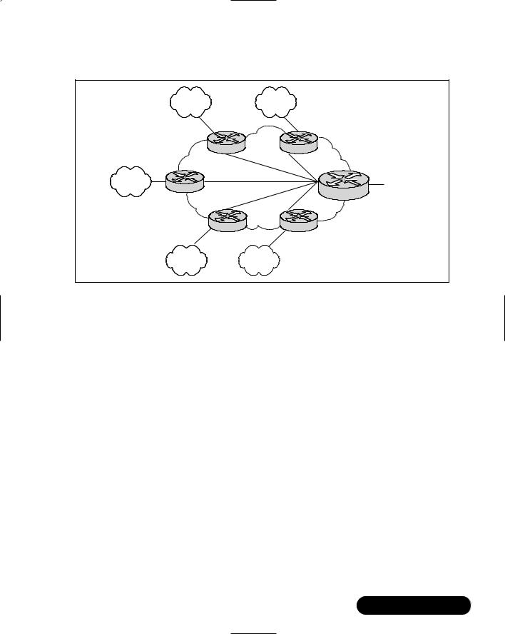
Star Topologies
The star topology (also known as a hub and spoke) is a grouping of network devices that has a single internetworking hub, and provides connections for the external cloud networks to the backbone and access to each other, although only through the core router. Figure 8.3 illustrates a packet-switched star topology for a regional internetwork.
One of the main advantages of a star topology is that there is simplified management and minimized tariff costs or tolls.Whereas tolls aren’t much of a factor
www.syngress.com
Designing the Infrastructure • Chapter 8 |
429 |
Figure 8.3 Star Topologies for a Regional Internetwork
Cloud |
Cloud |
|
|
Router |
|
Router |
|
Cloud |
Regional Packet- |
|
Connection |
|
Switching Network |
|
|||
Router |
Core Router |
to Backbone |
||
|
|
|
||
|
|
|
|
|
|
Router |
|
Router |
|
Cloud |
|
Cloud |
|
|
these days, they were in the past, and with some of the things that are happening politically, they could be again. However, there are significant disadvantages.
First, the core router is a single point of failure for the entire internetwork. Second, the core router can limit overall performance for access to backbone resources; the core may not be robust enough, or have enough bandwidth to handle all of the traffic from the external networks.Third, this topology is not very scalable, as there are generally only a certain number of ports on the core router.
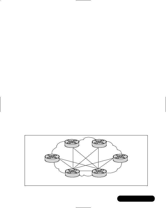
Fully Meshed Topologies
In a fully meshed topology, each routing node on the edge of a packet-switching network has a direct path to every other node on the cloud. Figure 8.4 illustrates this type of arrangement.
One of the best reasons for creating a fully meshed environment is that it provides for a high level of redundancy. A fully meshed topology helps to facilitate the support of all routing protocols, but it is not tenable in large packetswitched internetworks.
Some of the main issues are due to the large number of virtual circuits that are required (one for every connection between routers).There are also problems associated with the large number of packet and broadcast replications necessary for routing protocols or application traffic, and the configuration complexity for routers in the absence of multicast support in nonbroadcast environments.
www.syngress.com
430 Chapter 8 • Designing the Infrastructure
Figure 8.4 Fully Meshed Topology
Router |
Router |
Router |
Router |
Router |
Router |
Packet-Switching
Network
There is a middle ground, though; by combining fully meshed and star topologies into a partially meshed environment, you can improve fault tolerance without encountering the performance and management problems that are normally associated with a fully meshed internetwork.The following section discusses the partially meshed topology.
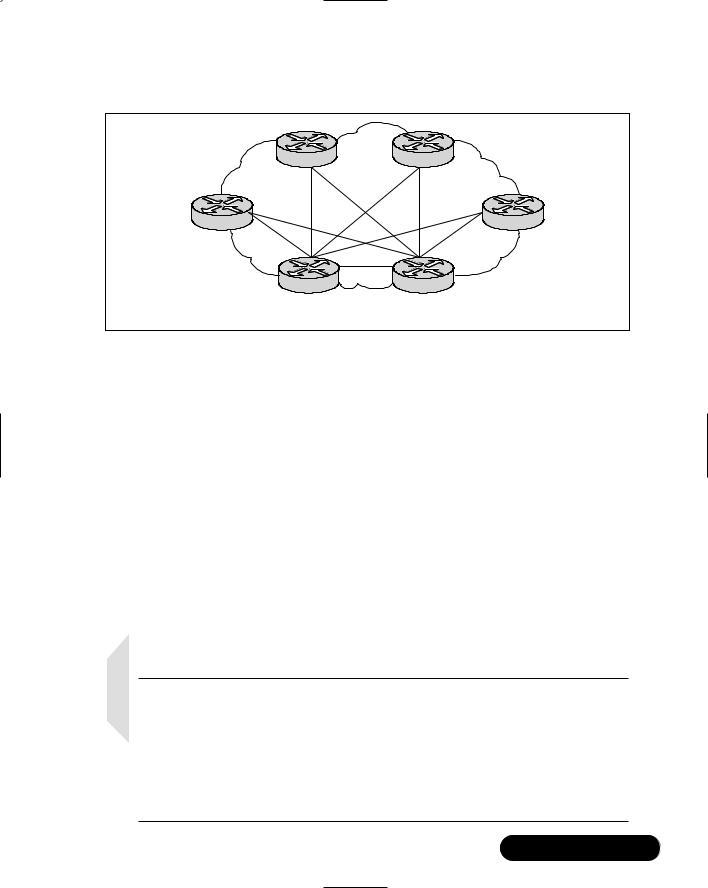
Partially Meshed Topologies
As discussed earlier, a partially meshed topology reduces several of the problems that are inherent in star and fully meshed topologies.There is a reduction in the number of routers within a region that need direct connections to all other nodes in the region. Not all nodes need to be connected to all other nodes. For a nonmeshed node to communicate with another nonmeshed node, it will send traffic through one of the hub routers.This is a lot like the star topology, but there is
a redundant path available in the event the hub router becomes inoperable. Figure 8.5 illustrates such a situation.
There are many forms of partially meshed topologies. Generally, partially meshed implementations provide the optimum balance for regional topologies in terms of the number of virtual circuits, their ability to provide redundancy, and their overall performance. By providing a greater amount of connectivity and high availability, you will be able to use your bandwidth more effectively.
www.syngress.com
Designing the Infrastructure • Chapter 8 |
431 |
Figure 8.5 Partially Meshed Topology
Router |
Frame Relay |
Router |
|
Network |
|||
|
|
||
Router |
|
Router |
Hub Router |
Hub Router |
(Redundant) |
(Redundant) |
Broadcast Issues
Broadcast traffic presents problems when it is introduced into a packet-service environment. Broadcasts are necessary for a node to reach multiple other node stations with a single packet when the sending node does not know the address of the intended recipient, or when the routing protocols needs to send hello packets and other miscellaneous services.
As an example, the level of broadcast traffic that is generated in an Enhanced IGRP environment depends on the setting of the enhanced IGRP hello-timer interval.The size of the internetwork determines other issues. In a small network, the amount of broadcast traffic generated by Enhanced IGRP nodes might be higher than with comparable internal gateway routing protocols that run on the Internet.
However, for large-scale internetworks, Enhanced IGRP nodes generate substantially less broadcast traffic than RIP-based nodes, for example.
NOTE
Usually, it is a good practice to manage packet replication when going over your design considerations. When integrating broadcast-type LANs (such as Ethernet) with nonbroadcast packet services (such as X.25), you should try to figure out where replication will cause bottlenecks within your network. With the multiple virtual circuits that are characteristic of connections to packet-switched environments, routers need to replicate broadcasts for each virtual circuit on a given physical link.
www.syngress.com

432 Chapter 8 • Designing the Infrastructure
Within a highly meshed environment, the replicating broadcasts can be resource intensive in terms of increased required bandwidth and number of CPU cycles. Because of this, highly meshed networks are impractical for large packetswitching networks. However, circuit meshing is essential to enable fault tolerance. You really need to balance the trade-offs in performance with requirements for redundancy. Also remember that as you scale your network, there will be other issues that fall within the same vein; as you add routing nodes, you will want to add redundancy, which will add at least two paths to your core infrastructure.
Performance Issues
When designing your WAN around a specific application service type, you should consider the characteristics of the virtual circuit. Sometimes the performance of a virtual circuit will depend on its capability to handle mixed-protocol traffic. Depending on how the traffic is queued and streamed from one node to the next, certain applications may require special handling. One solution might be to assign specific circuits to specific application and protocol types.
There are always going to be performance concerns for specific packetswitching services.That is why there is the ability to include Committed Information Rates (CIR) in Frame Relay internetworks and window size limitations in X.25 networks. (The CIR matches the maximum average rate per connection for a period of time.)
What is highly common within the ISP market is to sell guaranteed CIRs to your customers and give them the ability to “burst” (for a fee, of course) outside of the limits that they were given. As it is, a CIR is the minimum amount of bandwidth that your client is guaranteed at any point in time.The CIR is usually defined within the service level agreement (SLA) to which you and the customer agreed.
Frame Relay Internetwork
Design Considerations
A major concern when designing a Frame Relay implementation is scalability. As the number of remote clients and their links grows, your network must be able to grow to accommodate these growth spurts.The network must also provide a high level of performance, yet minimize support and management requirements.
Meeting all these objectives can be quite a feat.The following sections focus on some of the critical factors for Frame Relay internetworks, such as:
www.syngress.com

Designing the Infrastructure • Chapter 8 |
433 |
■Hierarchical design
■Regional topologies
■Broadcast issues
■Performance issues
The following are suggestions to provide a solid foundation for constructing scalable networks that can balance performance, fault tolerance, and cost. Again, I am only using Frame Relay as a template; it is not the only technology that you can use.
Hierarchical Design for
Frame Relay Internetworks
As discussed earlier in this chapter, the arguments supporting hierarchical design for packet-switching networks apply to hierarchical design for Frame Relay networks. Remember the three factors that lead us to recommend the implementation of a hierarchical design:
■Scalability
■Manageability
■Optimization of broadcast and multicast control traffic
One of the ways in which many Frame Relay vendors charge for services is by data link connection identifier (DLCI) numbers.These DLCI numbers identify a Frame Relay permanent virtual connection (PVC, also known as a permanent virtual circuit, which is the X.25 terminology).The DLCI number is locally significant, and defines the connection between Frame Relay elements.The number of Frame Relay PVCs within the network is highly dependent on what protocols are in use and actual traffic patterns.
To figure out how many DLCIs are going to be used within your environment, and how many will be mapped to your interfaces, depends on several factors that should be considered together:
■What protocols are being routed? Any protocol that is broadcast intensive will constrain the number of assignable DLCIs. For example, AppleTalk is a routed protocol characterized by high levels of broadcast overhead. Another example is Novell Internetwork Packet eXchange (IPX), which sends both routing and service updates, which results in
www.syngress.com

434 Chapter 8 • Designing the Infrastructure
higher broadcast bandwidth overhead. In contrast, IGRP is less broadcast intensive, because it will send routing updates less often (by default, every 90 seconds).You can modify the timer for IGRP, so it can become broadcast intensive if timers are modified to send updates more frequently.
■What are the levels of broadcast traffic? Broadcasts, such as routing updates, are one of the most important considerations when determining the number of DLCIs that can be defined.The amount and type of broadcast traffic will be a factor in your ability to assign DLCIs within this general recommended range.
■What is the speed of the connection? Broadcast traffic levels are expected to be high, so you should consider faster links and DLCIs with higher CIR and higher burstable limits.You should also consider implementing fewer DLCIs.
■Are there any static routes? If static routing is implemented, you can use a greater amount of DLCIs per line, because a larger number of DLCIs will help to reduce the level of broadcasting.
To assist in your design considerations, here are two forms of hierarchical design that you can implement:
■The hierarchical meshed Frame Relay internetwork
■The hybrid meshed Frame Relay internetwork
These designs have their advantages and disadvantages, and are compared in the following sections.
Hierarchical Meshed Frame Relay Internetworks
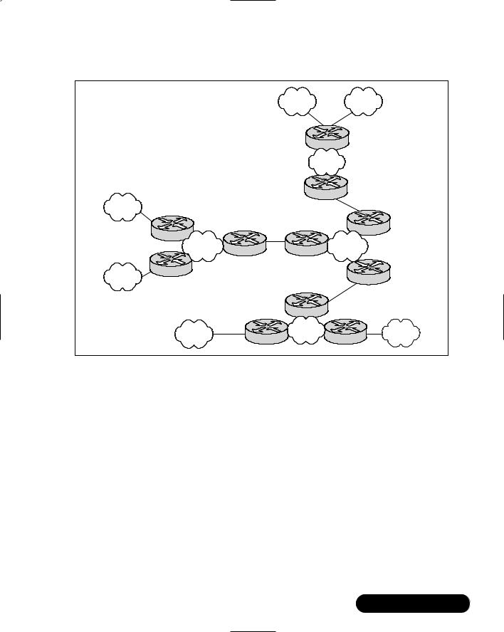
Implementing a hierarchical mesh for Frame Relay environments can assist you in avoiding implementing an excessively large number of DLCIs.This will allow for a more manageable, segmented environment.The hierarchical meshed environment features full meshing within the core PSDN and throughout the surrounding networks. Locating routers between network elements creates the hierarchy.
Figure 8.6 illustrates a simple hierarchical mesh.The internetwork shown illustrates a fully meshed backbone, with meshed regional internetworks and broadcast networks at the outer edges.
www.syngress.com
Designing the Infrastructure • Chapter 8 |
435 |
Figure 8.6 Fully Meshed Hierarchical Frame Relay Environment
|
|
X1 |
|
X2 |
|
|
|
Router |
|
||
|
|
Meshed |
|
||
|
|
Region X |
|
||
|
|
Router |
|
||
Y1 |
|
|
|
|
|
Router |
|
|
Frame |
Router |
|
|
|
|
|||
Meshed |
|
|
|
||
Router |
Router |
Relay |
|
||
Region Y |
|
||||
Backbone |
|||||
|
|
|
|||
Router |
|
|
|
|
|
Y2 |
|
|
|
Router |
|
|
|
|
|
||
|
|
Router |
|
|
|
Z1 |
|
Meshed |
|
|
|
Router |
Region Z |
Router |
Z2 |
||
|
|
|
|||
The advantage of the hierarchical mesh is that it scales well and helps to localize traffic. By placing routers between fully meshed portions of your network, you limit the number of DLCIs that need to be configured per physical interface, segment your internetwork, and make the network more manageable.
However, please remember these two issues when implementing a hierarchical mesh:
■Broadcast traffic and packet replication In an environment that has a many routers with multiple DLCIs per interface, there will be excessive broadcast and packet replication, which can impair overall performance. Due to a high level of meshing throughout a network, there will be excessive broadcasts and packet replication that will be a significant resource threat. In the core, where throughput requirements are typically high, the prevention of bandwidth loss due to broadcast traffic and packet replication is particularly important.
www.syngress.com
436Chapter 8 • Designing the Infrastructure
■Increased costs associated with additional router interfaces
When compared with a fully meshed topology, additional routers will be necessary to split the meshed core from the meshed edge networks. However, by implementing these routers, you are creating much larger networks that scale ad infinitum when compared to a fully meshed internetwork.
Hybrid-Meshed Frame Relay Internetworks
The cost-effective and strategic significance of the core network often forces network designers to implement a hybrid-meshed network for their WAN internetworks. A hybrid-meshed network is composed of redundant, meshed lines in the WAN core, and partially (or fully) meshed Frame Relay PSDNs on the network edge. Routers separate the two networks. Figure 8.7 illustrates such a hybrid arrangement.
Figure 8.7 Hybrid Hierarchical Frame Relay Internetwork
|
X1 |
Router |
|
|
Access Networks X1 and |
|
|
Fully Meshed |
|
|
|
|
||
X2 Also Use Partially |
|
|
|
|
|
Partially Meshed |
|
Backbone |
|
Meshed Topology |
|
Regional Internetwork |
Router |
Interconnected with |
|
|
Connected by Frame |
||
|
|
|
Point-to-Point |
|
Router |
|
Relay PSDN |
|
Leased-Lines |
|
Router |
|
|
|
Frame Relay |
|
|
|
|
Regional Network |
|
Router |
Router |
Router |
Router |
|
Router |
|
|
|
|
|
Point-to-Point |
|
|
|
|
Backbone |
|
Router |
|
X2 |
Router |
Router |
|
|
The hybrid hierarchical mesh designs can provide higher performance on the core because they can localize traffic and simplify the scaling of the network. Hybrid-meshed networks for Frame Relay can provide better traffic control in
www.syngress.com

Designing the Infrastructure • Chapter 8 |
437 |
the core and allow the backbone to be composed of dedicated links, which results in greater stability.
Some of the disadvantages of hybrid hierarchical meshes include the high costs associated with leased lines, and increased broadcast and packet replication traffic.
Regional Topologies for Frame Relay Networks
There are generally three accepted designs that are relevant for a Frame Relaybased packet service regional network:
■Star topology
■Fully meshed topology
■Partially meshed topology
Each of these topologies is discussed in the following sections. Generally, I have emphasized partially meshed topologies as those that are integrated into a hierarchical environment; star and fully meshed topologies are discussed more for their structural context.
Star Topologies
Star topology was addressed earlier in the section,“Possible Types of Topology Design.” Star topologies are attractive because they minimize the number of DLCIs that are required, which will result in a lower-cost solution. However, some inherent issues are associated with the star topology because bandwidth limitations. In an environment in which a backbone router is attached to a Frame Relay cloud at 768 Kbps, and the remote sites are attached at 256 Kbps, there will be some throttling of traffic coming off the core that is intended for remote sites.
A star topology does not offer the fault tolerance that is necessary for many networking situations. For example, if the link from the hub router to a specific cloud router is lost, all connectivity to that router is lost.
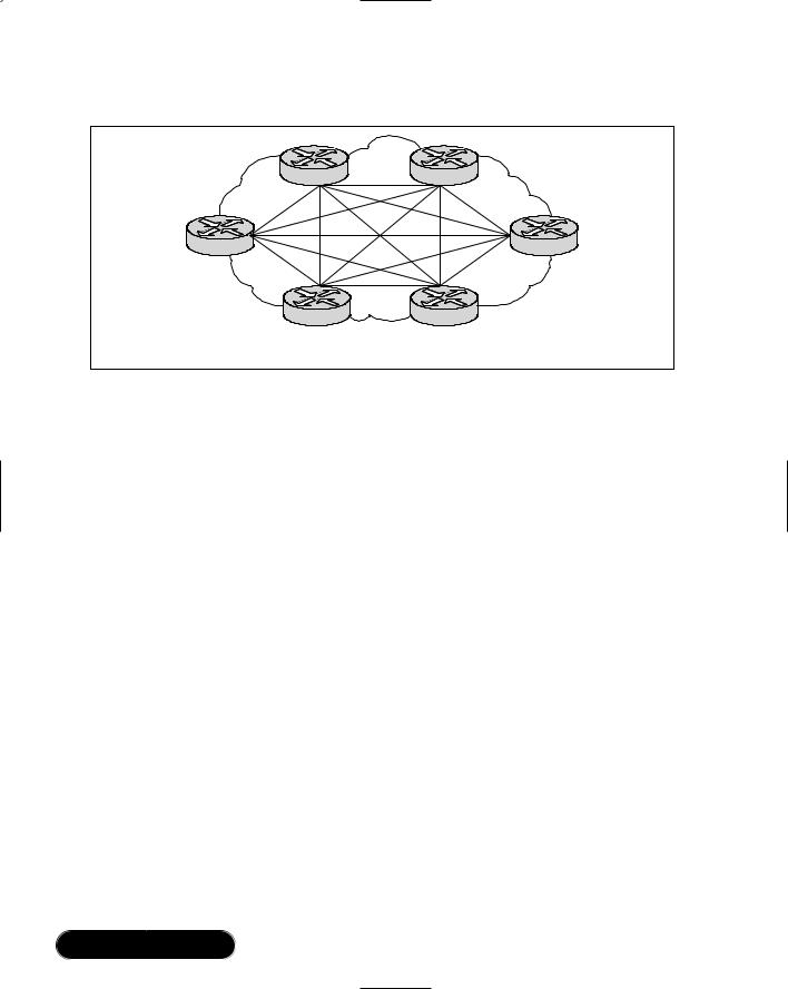
Fully Meshed Topologies
A fully meshed topology requires that every routing node connected to a Frame Relay network is logically linked by an assigned DLCI to every other node on the cloud.This topology is not easy to manage, support, or even implement for larger Frame Relay networks for several reasons:
www.syngress.com
438Chapter 8 • Designing the Infrastructure
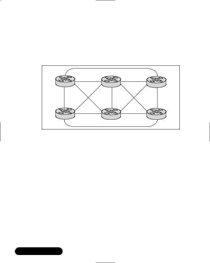
■Large, fully meshed Frame Relay networks require many DLCIs.There is a requirement for each logical link between nodes to have a DLCI. As shown in Figure 8.8, a fully connected topology requires the assignment of [x(x-1)]/2 DLCIs, where x is the number of routers that will be directly connected.
Figure 8.8 Fully Meshed Frame Relay Network
Router |
Router |
Router |
|
DLCIs |
|
Router |
Router |
Router |
■Broadcast and replication traffic will clog the network in large, meshed Frame Relay topologies. Routers tend to use Frame Relay as a broadcast medium. Every time a router sends a multicast frame (such as a routing update, or spanning tree update), the router will copy the frame to each DLCI for that Frame Relay interface.
This makes fully meshed topologies highly nonscalable for all but relatively small Frame Relay networks.
Partially Meshed Topologies
By combining the star topology and the fully meshed topology, you will be able to implement a partially meshed topology. Partially meshed topologies are usually recommended for Frame Relay networks that span regional environments as they can provide fault tolerance (through redundant star routers) and are less expensive to implement than a fully meshed environment. As a rule, you should implement at least minimum meshing to eliminate single point-of-failure issues.Virtual interfaces allow you to create networks using partially meshed Frame Relay designs, as shown in Figure 8.9.
www.syngress.com

Designing the Infrastructure • Chapter 8 |
439 |
Figure 8.9 A Twin-Star Router, Partially Meshed Network
Router |
Frame Relay |
Router |
|
Network |
|
Router |
|
Router |
Star Router |
Star Router |
(Redundant) |
(Redundant) |
To create this type of network, you need to assign multiple virtual interfaces (these are considered logical addresses) to individual physical interfaces. In this manner, DLCIs can be grouped or separated to maximize their functionality. As an example, a small, fully meshed cloud of Frame Relay networked routers can travel over a group of four DLCIs that are clustered on a single virtual interface, but a fifth DLCI on a separate virtual interface can provide the connectivity to a completely separate network.This all happens over a single physical interface that is connected to the Frame Relay cloud.
Broadcast Issues for Frame Relay Networks
Routers treat Frame Relay as a broadcast media, which means that each time the router sends a multicast frame (such as a routing update, or a spanning tree update), the router must replicate that frame to each DLCI that is associated with the Frame Relay physical interface.This broadcast and replication traffic results in substantial overhead for the router and for the physical interface itself.
Consider an IP RIP environment with multiple DLCIs configured for a single physical serial interface. Every time a RIP update is detected, which occurs every 60 seconds, the router must replicate it and send it down the virtual interface associated with each DLCI.
www.syngress.com

440 Chapter 8 • Designing the Infrastructure
NOTE
There are several ways to reduce broadcast and replication traffic within your network. One of the most efficient is to implement some of the more efficient routing protocols, such as Enhanced IGRP, and to adjust timers on lower-speed Frame Relay services.
Creating a Broadcast Queue for an Interface
When it comes to designing and implementing a very large Frame Relay network, you may come across performance issues when you have many DLCIs that terminate in a single router or that access a server that must replicate routing updates on each DLCI.What occurs is that these updates consume bandwidth and can cause noticeable latency in user traffic.These updates can also consume interface buffers, which will lead to packet loss, and therefore loss of user data and routing updates.
There is a way to avoid these problems, though.You can create a special broadcast queue on an interface.The broadcast queue can be managed independently of the normal interface queue, because it has its own buffers, and the size and service rates of traffic can be configured.
A broadcast queue has a maximum transmission rate (throughput) limit applied to the interface, which is measured in both bytes per second and packets per second.This queue is regulated to make certain that no more than the configured maximum bandwidth is provided.The broadcast queue also has priority when transmitting at a rate that is below the configured maximum to guarantee the minimum bandwidth allocation for the interface.These transmission rate limits are implemented to avoid flooding the interface with broadcasts and replication traffic.
Committed Interface Rates
When you implement Frame Relay packet-switched networks, external service providers create a CIR that measures in bits per second.This is one of the main metrics. CIR is the maximum permitted traffic level that a carrier will allow on a specific DLCI across its packet-switching environment.The CIR can be anything up to the capacity of the physical media of the connecting link.
www.syngress.com

Designing the Infrastructure • Chapter 8 |
441 |
One of the drawbacks associated with the CIR is that there are relatively few ways to automatically prevent traffic on a line from exceeding the maximum bandwidth. Although Frame Relay uses the Forward Explicit Congestion Notification (FECN) and Backward Explicit Congestion Notification (BECN) protocols to control traffic in the Frame Relay network, there isn’t a standardized mapping between the Frame Relay (link) level and most upper-layer protocols at this time.
What really happens when the specified CIR is exceeded depends on the types of applications that are running on your network. For instance,TCP/IP has something called a backoff algorithm that will see dropped packets as an indication that there is congestion, and sending hosts might reduce output.You should consider the line speeds and what applications are going to be running on your network.
There is a way to buffer Frame Relay traffic so that it can handle instances when traffic exceeds the CIR for a given DLCI.These buffers spool excess traffic to reduce packet loss, especially if you are using a vigorous transport protocol such as Transmission Control Protocol (TCP). Even with these buffers in place, overflows can occur. Remember that routers have the ability to prioritize traffic; Frame Relay switches do not.
You can also specify which packets have low priority or are not time sensitive, so that if there is a need to drop traffic, they will be the first to be discarded when there is congestion.The method that allows a Frame Relay switch to identify these packets is within the packet itself and is known as the discard eligibility (DE) bit.
The Frame Relay network must be able to interpret the DE bit, though, so that there is an action taken when the switch encounters a DE bit during heavy congestion times. Sometimes, networks will take no action when the DE bit is set; at other times, networks use the DE bit to determine which packets to discard. Probably the best way to implement the DE bit is to set it to determine which packets should be dropped first, but also which packets have lower time sensitivity. By doing this, you can define DE lists that will identify the types of packets that are eligible to be discarded, and you can also specify DE groups to identify the DLCI and interface that is being affected.
You can specify DE lists by the protocol and/or the interface used. Characteristics such as fragmentation of the packet, a specific TCP or User Datagram Protocol (UDP) port, an access list number, or a packet size can also be factors that you should consider as DE.
www.syngress.com

442 Chapter 8 • Designing the Infrastructure
NOTE
To avoid packet loss, be sure that you understand what types of applications are going to be on your network and how dropped packets affect them. Try to implement unacknowledged application protocols (such as packetized voice and video) carefully; these protocols have a greater chance of buffer overflow. Dropped packets are okay in voice and video applications, whereas data applications such as ERP should not drop frames.
By defining separate virtual circuits for your different types of traffic, and specifying the queuing and an outbound traffic rate, you can give the customer a guaranteed bandwidth for each of your applications. By being able to specify different traffic rates for different virtual circuits, you can perform virtual time division multiplexing (TDM).
You can also ease congestion and data loss in the network by throttling the outbound traffic that comes from high-speed lines in central offices, and go to low-speed lines in remote locations.This enhanced queuing will also help to prevent congestion that causes data loss.This type of traffic shaping can be applied to both PVCs and SVCs.
Capacity Planning for
Your Infrastructure
Have you ever tried to install a server, and there just isn’t a spare rack, or even an available network port? This is usually an issue for service providers who did not plan properly for explosive growth. A ripple effect of this is that the network probably is staggering with the amount of clients that were added. In this section, we discuss some best practices for implementing a capacity plan.
Connection and Expansion
Capacity planning is an issue that you will need to address, along with the design and implementation procedure. If you have a general idea of where you stand for number of servers and expected growth, you can use those as a baseline for the capacity of your network.The reason that I say “baseline” is that many things can happen in the business world over the course of six months that might cause
www.syngress.com

Designing the Infrastructure • Chapter 8 |
443 |
your design to be underpowered and/or oversubscribed. Depending on the size of the current and expected network, there should be a padding area of approximately 10 to 15 percent for unexpected growth.You should reevaluate capacity after every new customer you install.
Best Practices
One of the best practices for planning is to map out where the different customer areas are located, and what the server count is going to be. Once these figures are determined, decide if the servers need one data link or multiple connections.
With the number of connections decided, you now need to plan on subscription and maximum bandwidth provisions of the network. Sounds impressive, huh? It really isn’t that difficult.What you are doing is calculating the aggregate average bandwidth of the network devices located on the segment.With these calculations in place, you can plan whether the segment is powerful enough to support the clients and resources on a given network.
So, how do you calculate the aggregate average bandwidth? The calculations are based on network topology, users’ traffic patterns, and network connections. Ask questions such as,“What type of links should we use to connect the clients to the data center? What should the bandwidth requirement be for the backbone?”
You need to plan what type of link goes to each client, so that it has the proper bandwidth, yet does not allow for the monopolization of network resources, and/or completely shut down the network with oversubscription of a segment. Monopolization of a segment occurs when a user has the equal bandwidth of a resource (such as an application server), and the application takes all of the available bandwidth and maintains the trunk.This will not allow other clients to access the resource.
Oversubscription of a segment occurs when multiple customers use all of the application resource’s bandwidth, and therefore, other clients are unable to access the resource.While the two symptoms just described result in the same conclusion, they are different.The segment in a monopolized environment runs consistently, whereas the segment that is oversubscribed may shut itself down because it cannot pass traffic due to multiple requests flooding the buffers on the switches and routers.
With all of this information, you should get an idea for the type and capacity of network equipment you need to deploy at each location. Further concerns for planning capacity are based on factors such as which protocol you use, the addressing schemes, the geography, and how these fit the topology of the network.
www.syngress.com

444 Chapter 8 • Designing the Infrastructure
Protocol Planning Concerns
The following section provides details on how to choose a protocol to best match your environment.With proper planning and implementation, any choice will work. By determining the physical layout of the network, you will be able to map the correct topology and form a logical addressing scheme that will grow as your network grows.
Routing Protocols
Choosing routing protocols and their configuration are important parts of every network design.You must be prepared to spend a significant amount of time implementing your policies for the network to provide optimal performance. Routing protocols are a fundamental component of networking and creating a reachable network that can transfer data.
If designed properly, the network will build routing tables and maps that you can use to see adjacent routers and their status.There is also the ability to see network paths, congestion, and bandwidth of those links.This information helps in deciding on the optimal network paths.
The more complex routing protocols allow you to add secondary metrics. Some of those metrics include reliability, delay, load, and bandwidth. Using these metrics, the router can make these routing decisions dynamically.
The basic difference in the various routing protocols lies in the sophistication of their decision-making capabilities and metric support.This is one of the main factors to consider when choosing a protocol to match the characteristics of your network.
There are two types of routing protocols, internal and external. Internal protocols are those that you would implement within your network infrastructure, and are controlled completely within that domain. Conversely, external protocols work with external domains, such as the Internet or other ISP networks.These protocols are designed to protect your domain from external errors or misrepresentation.To read more about internal and external protocols, visit the Internet Engineering Task Force’s site (www.ietf.org).
Interior Gateway Protocols
How do you decide on which interior protocol to use? The following section explains some of the inherent differences that are implemented in each of the interior protocols. Some are self-explanatory, and some are just more complex.
www.syngress.com
Designing the Infrastructure • Chapter 8 |
445 |
I hope that this section will clarify some of the terms and allow you to make reasonable, well thought-out decisions.
Let’s deal more with interior protocols, since those are the ones that you may have used less in your ISP environment.With the exception of OSPF and IS-IS, the interior routing protocols described are distance-vector protocols, and they use distance and next-hop data to make their routing and forwarding decisions.
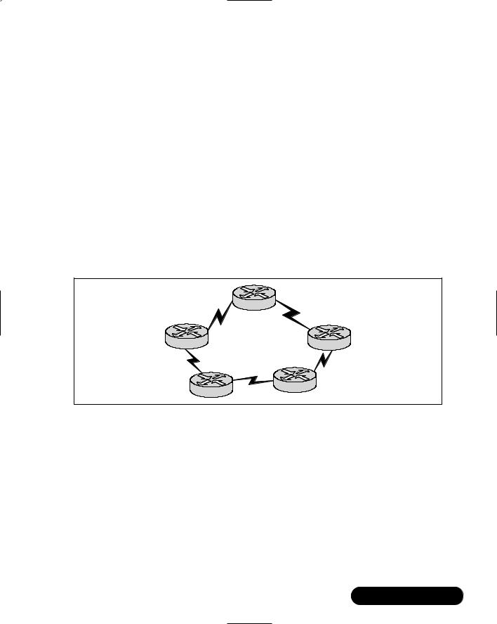
Some distance-vector protocols are very simplistic and don’t scale well in larger environments. One example is RIP, which uses hops (the number of connections between it and its destination) as its determining factor.The largest hop count before it disregards the packet is 15, making it one of the least scalable protocols. Another drawback to RIP is that it does not take into account varying available bandwidth. If, for example, you have a packet that needs to get from network A to network D, RIP will take the path with two hops, rather than the path with two hops but higher speed (Figure 8.10).
Figure 8.10 RIP and Routing Decisions
T1 |
Router B |
T1 |
|
||
Router A |
|
Router C |
56k
T1
Router E |
56k |
Router D |
|
If your network is fairly simple in terms of the topology and number of routers, a distance-vector protocol such as RIP or IGRP (discussed later in this chapter) could work fine. If you’re running a multivendor network, RIP, RIPv2, IS-IS, and OSPF are common protocols across many vendors’ router implementations.
This chapter lists what is available for use in a semichronological order, as this is probably how you will see them listed in other reference manuals. Some of the strengths and limitations for each protocol are also listed.
www.syngress.com
446 Chapter 8 • Designing the Infrastructure
Routing Information Protocol
The Routing Information Protocol (RIP) was derived from Xerox Corporation’s XNS for IP networks. It supports IP and IPX networks.
Strengths:
■Still viable in networks that use a constant internal subnet
■Usable on most vendors’ equipment
■Low cost (generally free from most vendors)
Weaknesses:
■Scalability is minimal (15-hop maximum)
■Path determined by hop count, and may take best path
■Broadcasts full routing table frequently, wasting bandwidth
■Cannot handle variable-length subnet masks (VLSM)
Interior Gateway Routing Protocol (Cisco Only)
The Interior Gateway Routing Protocol (IGRP) was created by Cisco for Cisco IP and OSI networks. It supports IP and OSI networks.
Strengths:
■Uses multiple metrics in decision making
■Fast convergence
Weaknesses:
■Runs only on Cisco equipment
■Broadcasts routing table frequently, wasting bandwidth
Open Shortest Path First
The Open Shortest Path First (OSPF) was developed by the IETF for IP networks. It supports IP networks.
Strengths:
■Usable on most vendors’ equipment
■Only broadcasts routing table when changes are made
www.syngress.com

Designing the Infrastructure • Chapter 8 |
447 |
Weaknesses:
■Uses only bandwidth as a metric
■Restricts some topologies
Integrated Intermediate System-to-Intermediate System
The Integrated Intermediate System-to-Intermediate System (IS-IS) was developed by IETF for OSI and IP networks. It supports IP and OSI networks.
Strengths:
■Usable on most vendors’ equipment
■Only broadcasts routing table when changes are made
■Fast convergence
Weaknesses:
■Uses only bandwidth as a metric
■Restricts some topologies
RIPv2
RIPv2 was developed by the IETF for IP networks. It supports IP and IPX networks.
Strengths:
■Added authentication and multicast ability to RIP
■Usable on most vendors’ equipment
Weaknesses:
■Scalability is minimal (15-hop maximum)
■Only uses bandwidth as metric
Enhanced Interior Gateway Routing Protocol (Cisco Only)
The Enhanced Interior Gateway Routing Protocol (EIGRP) (Cisco only) was designed by Cisco for multiprotocol Cisco networks. It supports IP, IPX, and AppleTalk networks.
www.syngress.com

448 Chapter 8 • Designing the Infrastructure
Strengths:
■Incremental updates to reduce broadcast traffic
■Supports VLSMs
■Uses multiple metrics
■Fast convergence
■Retains backward compatibility with IGRP
Weakness:
■Works only with Cisco equipment
External Protocols
There is really only one external protocol to talk about, the Border Gateway Protocol (BGP).There have been entire books written on BGP, and several companies make their living working with BGP exclusively.These companies are highly paid, because you do not want to create incorrect BGP parameters and advertisements.These common mistakes will definitely adversely affect your network.
I will not go into any detail here, because if you have BGP and it is up and running, you most assuredly do not want to mess with it.
Choosing the Right Interior Protocol
Using the previous references that explained the differences inherent with the interior protocols, it is time to address which networking protocol will be best for your network.There are several considerations to take into account for your choices.You want the protocol to add functionality, you want it to be scalable, you want it to easily adapt to changes that will be implemented, you want it to be manageable, and you want it to be cost effective.
Scalability is an issue that will keep cropping up.You want your design to meet current and future growth.What happens if you decide to implement RIP, and then exceed the hop count within your own network? Preplanning will save you some massive restructuring headaches later in the development of the infrastructure.
Adaptability to new technologies is essential.With the world moving toward higher and higher bandwidth usage, you must take into account that what you design must be readily adaptable for future technologies (e.g.,Voice over IP (VoIP) and video traffic) that will possibly be implemented.This is an area where adding value to your network will save your company money in the long run.
www.syngress.com

Designing the Infrastructure • Chapter 8 |
449 |
Another key concern is the manageability of the network.You are going to get into an area where there is more network traffic than bandwidth, and you are going to want to manage traffic and to some extent monitor the usage of the links that are on your network.With that criteria in mind, plan on protocols that will be more beneficial to you and the management of the network.
Finally, one of the toughest areas when choosing a routing protocol is cost effectiveness. Some of the protocols can only run on Cisco equipment because they are proprietary.While RIP will run on most equipment, and is very cost efficient, the network would have to be scaled down so that it could be properly implemented. A protocol such as EIGRP would be fantastic in a larger-scale environment, but it only works with Cisco equipment, so you need to keep that in mind if you have legacy equipment you are planning to phase out.
Route Selection
So why are we talking about route selection? It seems somewhat silly if there is only one route to the destination.The question is, what happens if that route should fail? What about using other routes to allow more traffic and less congestion? These reasons are why most networks are designed with multiple routes (redundancy and load balancing), so there is always an alternate connection in case of failure or to alleviate traffic issues. Routing protocols use metrics to select the best route based on weighted decisions, from groups of existing routes.
Metrics are values that can be assigned and weighted to make decisions on routing paths within a network. Metrics are assigned characteristics or a set of characteristics on each link/route of a network.When traffic is passed along a link, it the network equipment makes a choice on how to route the traffic by calculating values of the metrics and assigning the traffic to the selected path.
Metrics are handled differently depending on the routing protocol. Most of the routing protocols can use multiple paths if they are equal cost. Some protocols can use paths that have routes that are not cost equivalents. By implementing multiple paths, you can use load balancing to improve bandwidth allocation.
With a multiple path design, there are two widely used ways for packet distribution: per-packet load balancing and per-destination load balancing.
Per-packet load balancing uses all possible routes in proportion to the route metrics.What this means is that if all routes are equal cost, it will cycle through them in a “round robin” selection scheme, where one packet is sent to each possible path that is available. Routers are defaulted to this method when fast switching is disabled.
www.syngress.com

450 Chapter 8 • Designing the Infrastructure
Per-destination load balancing uses routes based on what the destination. Each destination is assigned an available route and maintains that route for future use.This way, traffic tends to arrive in the proper order. Routers default to this method when fast switching is enabled.
NOTE
TCP can accommodate out-of-order packets, and there will always be some on multipath networks. Excessive out-of-order packets can cause performance issues, so don’t go overboard on the redundant load balancing. Make sure to have at least one extra path between segments and NO MORE if redundancy is an issue.
Preplanning these rollouts will save aggravation and long nights of troubleshooting. Sometimes it is best to sit down, create a matrix with these considerations, and cross-reference what will be best for your network.Try to use a single interior routing protocol for your network. Sometimes this is not possible, so in those instances, plan for the best protocol mesh and implement as cleanly as possible.
The best advice that I offer is,“keep it simple.” Complexity is not a good thing in network design.You want a stable, simple network. Now, on to the next decision-making process, addressing.
Addressing Considerations
The addressing scheme is dependent on several variables. Since most companies are now creating firewalls and implementing Network Address Translation (NAT) and/or Port Address Translation (PAT) to their public address space to conserve addresses, you have to figure out how to implement your addresses in a logical manner. Since NAT is so popular, private addressing is almost completely up to you.The three private address spaces are:
■Class A 10.x.x.x
■Class B 172.16.x.x
■Class C 192.168.x.x
www.syngress.com

Designing the Infrastructure • Chapter 8 |
451 |
These are private addresses, and cannot be routed on the Internet. Using subnet masks will allow you to configure Network and Host IDs to suit your needs.
Since addressing is important, and time consuming, you want to plan allocation of addresses as neatly as possible so you have to readdress your network as little as possible. Plan on how you want to slice up the company, whether it is by site, location, department, telecommuter, and so forth. If you are using a public address scheme, conservation is key. If you are using a private addressing scheme, you should focus on layout. Deployment should be in a logical and readily understood manner for public and private addressing.You want to keep similar users as well and similar resources together.
Set aside address space for current and potential (have I said those words before?) users. If you want to keep all of the servers in one address space, set aside enough for future growth. Generally, you should group users with similar needs in similar locations (with the advent of VLANs, this is not the major concern it was in the past). Remember that when you add subnets, you need to place routers between subnets that cannot speak to each other.
Since the network doesn’t physically exist at this point in time, be sure to revise all of your ideas on paper.This will help for the actual implementation. Another way to help segment traffic and design your addressing scheme is by topology.
Topology
The topology of a network is defined by sets of routers and the networks to which they connect. Routing protocols can also establish a logical topology depending on implementation.
TCP/IP requires the creation of a hierarchical topology that establishes a Core layer, a Distribution layer, and an Access layer. For example, OSPF and IS-IS protocols use a hierarchical design.The hierarchical topology takes precedence over any topology created through address segmentation.Therefore, if you choose a hierarchical routing protocol, you should also create the addressing topology to reflect the hierarchy. If you decide to use a flat routing protocol, the addressing will create the topology.
There are two regularly accepted ways to assign addresses in a hierarchical network.The easiest way is to assign a unique network address to all network areas (including the core). A more complex way is to assign ranges of addresses to each area. Areas should be comprised of contiguous addresses for networks and
www.syngress.com
452 Chapter 8 • Designing the Infrastructure
hosts. Areas should also include all the router interfaces on any of the included networks. By doing so, each area maintains its own topology database, because all interfaces run a separate copy of the basic routing algorithm.
Flat networks were originally campus networks that consisted of a single LAN to which new users were added.This LAN was a logical or physical cable into which the network devices connected. In the case of Ethernet, all the devices shared the half-duplex 10 Mbps available.The LAN was considered a collision domain, because all packets were visible to all devices on the LAN; therefore, they were free to collide, given the carrier sense multi-access with collision detection (CSMA/CD) scheme used by Ethernet.
A bridge was inserted when the collision domain of the LAN became congested.This allowed a segmentation of traffic into several collision domains, because a bridge is a store-and-forward packet switch.With this ability to cut collision traffic, network throughput increased.The drawback is that bridges pass all traffic, including, flood broadcasts, multicasts, and unknown unicasts, to all segments.
All the bridged segments in the campus together form a single broadcast domain.The Spanning Tree Protocol (STP) was developed to prevent loops in the network and to route around failed connections.
Configuring & Implementing…
The STP Broadcast Domain
There are some issues with the STP broadcast domain. It has a high time threshold for convergence, typically 40 to 50 seconds. It allows for nonoptimized paths to exist. Redundant links carry no data because they are blocked. Broadcast storms affect the whole domain, and each network host must process all traffic. Security is limited within the domain, and troubleshooting problems is time consuming. New versions and options can reduce convergence time.
Broadcast traffic sets a practical limit to the size of the broadcast domain. Managing and troubleshooting a bridged campus becomes harder as the number of users increases because it adds to the broadcast domain. One misconfigured or malfunctioning workstation can disable an entire broadcast domain for an extended period of time, as it is generally hard to locate.
www.syngress.com

Designing the Infrastructure • Chapter 8 |
453 |
NOTE
The 80/20 traffic rule has been steadily changing due to the rise of intranets and distributed applications. With new and existing applications moving toward a distributed applications and storage model, which are accessed though Web retrieval, the traffic pattern is going toward the 20/80 model, where only 20 percent of traffic is local to the workgroup LAN, and 80 percent of the traffic is destined for a nonlocal domain.
Application and Network Services
Knowing the various network applications that will be on the wire is essential to the planning and design of your new network.You need to take into account all of the different types of protocols, ports, and bandwidth that will be used on the wire when running different programs. For instance, standard file and print traffic has far less overhead than database and backup applications do. Each program behaves in its own way, and you need to anticipate the behavior in order to design the network properly.
Make a list of the applications that will be running on the wire, and remember, be thorough! Make sure that you take into account every possible traffic generator (whether it is an application or a network device) that you can think of, no matter how trivial, and add it to the pile of your bandwidth calculations. Make sure also to give each application its proper “weight” in your calculations.
For instance, it is highly doubtful that people will be printing 100 percent of the time on the network, so make sure that you apply the proper percentage bandwidth subscription and utilization in your calculations as to how much time you will see the traffic.
Although this seems like a tedious task, it is well worth the exercise. Remember, the customer will be extremely unhappy with poor performance, and in all likelihood, you, the provider, will be the one blamed if the bandwidth is choked on the first day of the new network rollout.Try to overestimate the amount of bandwidth required at the worst times of traffic by about 20 percent. That will always lead to a safe estimate of bandwidth.
www.syngress.com

454 Chapter 8 • Designing the Infrastructure
Designing the Data Center Network
When designing the data center, you should build the network as a modular building block using multilayer switching.This way, you can segment the traffic so that it goes over specific bandwidths. For example, the Gigabit Ethernet trunk carries the server-to-server traffic, and the Fast EtherChannel trunk carries the backbone traffic, so all server-to-server traffic is kept off the backbone, which has performance and security advantages.
Data centers should have Virtual Router Redundancy Protocol (VRRP) redundancy between the multilayer switches, with access lists used to control access policy to the data center.With this setup, the core switches are separate from the distribution switches, thereby cutting down on broadcast domains and allowing for better throughput.
Note that when using the Hot Standby Router Protocol (HSRP) (Cisco specific) or Virtual Router Redundancy Protocol (VRRP), which can also add redundancy, you should consider implementing Fast EtherChannel so you can scale bandwidth from Fast Ethernet, and from Gigabit Ethernet to Gigabit EtherChannel.You should also consider using adaptive load balancing for high availability.
Terminal Data Centers
One of the benefits of using the Windows 2000 software platform is the built-in capability to use Terminal Server on the network.Terminal Server is the Microsoft version of thin-client technology that allows the workstations to receive a video snapshot of the desktop running on another machine. and control that machine remotely.
The benefit of this is so that bandwidth-heavy applications such as database and other query-based applications need not send the queries back and forth over the entire network on the “slow”WAN links. Rather, they have access to the “client” machine via high-speed switched links, and users on the network will be accessing the database applications as if they are right next to the database servers on the switch.
This technology has become increasingly popular over the last couple of years, as bandwidth has become a premium on the WAN links. Microsoft has built this technology into Windows 2000 so that any Win2K server can activate this remote control capability.
www.syngress.com

Designing the Infrastructure • Chapter 8 |
455 |
Application-Aware Networking
ASPs who want to deploy their applications need to realize that their success of mission-critical applications over both the internal LAN and clientele WAN is achieved by defining network policies, which assist in the apportioning of network resources with business objectives.These policies are then enforced with the creation of a Quality of Service (QoS) method for their application and bandwidth considerations.Without these QoS controls in place, nonvital applications and services can quickly overwhelm network resources by taking the available resources away from those applications that you are selling and causing poor customer satisfaction with your product.
When taking into account design considerations, remember that the ability to provide an end-to-end application that has prioritization within a LAN will need specific features that are dependent on where the networking device is located.
In a service provider environment, Access layer devices should deliver the following capabilities:
■Traffic detection The ability to identify types of applications.
■Admission control The ability to restrict application traffic.
■Traffic classification The ability to classify traffic, based on application type, destination, or physical port.
Traffic Detection and Classification
Traffic detection uses Layer 4 IP UDP and TCP port numbers. A switch that is able to examine a packet and identify the UDP and TCP port numbers can use this information to identify the application that is using that packet. A switch can then compare a packet that is being used to run a nonmission-critical application or service, such as email, against a packet that is running an application that is considered mission critical and classify it appropriately.
Admission Control
Admission control is provided by a mechanism that can reject or remove applications based on user-defined policies. For example, a client can define a policy to temporarily stop the transmission of email packets, so that the mission-critical applications can use the necessary resources.
www.syngress.com
456 Chapter 8 • Designing the Infrastructure
Admission control can also be used to provide the following benefits:
■During network congestion, you can specify that a specific application (e.g., video or multimedia traffic, which is usually considered bandwidth intensive) be dropped for the congestion period.
■You can bar specific applications from entering the network, which would save network bandwidth.
Traffic Classification
Traffic classification uses traffic detection to identify what applications are running.These applications can then be classified based on their user-defined policy. This classification will provide a tag that identifies the priority of the packet.This classification information is carried within the precedence bits of the IP packet. The classification technique that uses the IP precedence fields is commonly referred to as Type of Service (ToS). If you are going to use either Cisco Systems Inter-Switch Link (ISL) or 802.1Q, this is usually referred to as Class of Service
(CoS).
When using the IP precedence (which uses Layer 3) as the classification tag, you can deliver a QoS identifier that is independent of the transmission technology that is allowing for the mapping of QoS across disparate media types such as Ethernet and ATM.
ISL and 802.1Q use Layer 2 technologies that are more suitable to campus deployment across Ethernet networks that aren’t totally IP based. Unlike Layer 2 classification (ISL and 802.1Q), Layer 3 classification (ToS) has the ability to provide consistent end-to-end classification for a packet as it negotiates through LAN/WAN and intranet/Internet borders.
In the ideal environment, packet classification should only happen once. Both ISL and 802.1Q have a three-bit field that can provide up to eight priority levels, which helps in delivering consistent priority-level maps between technologies.
Traffic classification provides the following benefits to an ASP:
■It can provide a tag that will identify the priority assigned to each packet.This gives devices that are downstream the information they need to prioritize packet traffic.
■It provides the mechanism that can reclassify packets based on policy. As an example, when a client’s workstation applies a high priority to multimedia applications using traffic classification and detection, the
www.syngress.com

Designing the Infrastructure • Chapter 8 |
457 |
application, might be reclassified to a lower priority, depending on the implemented network policy.
In the Distribution and Core layers of a network, the devices should support the following features:
■Congestion avoidance The ability to drop certain packets based on their classification or policy during periods of network congestion.
■Scheduling The ability for the network equipment to show traffic transmission preference, based on classification of the application or the policy of the network.
Congestion Avoidance
By implementing Weighted Random Early Detection (WRED), you can add congestion avoidance in your infrastructure. Congestion avoidance can take advantage of TCP windowing to slow lower-priority application traffic before network congestion can affect the higher-priority applications.WRED is based on the output queues of the network device.
When network traffic increases, the chances of network congestion increases, because the buffers begin to fill. Eventually, the buffer will overflow and packets will be dropped in an unrestrained fashion.TCP traffic tends to increase its rate of data transmission; until packets are dropped or the maximum TCP transmit size is reached.When a data transmission mismatch happens (such as packets from a Gigabit Ethernet port destined for a FastEthernet port) the device’s buffers will begin to fill.
By dropping packets, random early detection (RED) helps to prevent a buffer overflow from randomly dropping packets, which can adversely affect application performance.WRED enhances RED by specifying which packets are dropped when they reach a buffer’s threshold.
There are generally three classes to packet classification: premium, standard, and DE. Mission-critical applications are normally mapped to the premium class, while all other traffic would be mapped to the standard threshold. If the buffer reaches 60 percent of full capacity, packets that belong in the standard class would begin to be randomly dropped. As the buffer continues to fill, the drop rate for the standard class applications will also increase.The premium service may be configured to not drop those packets until the buffer has reached 90 percent of its full capacity.
www.syngress.com

458 Chapter 8 • Designing the Infrastructure
Since it is harder to reach the higher thresholds (unless the network becomes overly congested due to a large amount of higher priority applications), higherpriority applications will continue to have end-to-end connectivity and performance. Consequently, traffic that is considered mission-critical is unaffected by applications with a lower priority.
Scheduling
In a switch, there is a switching fabric with a finite amount of backplane and time to transmit packets out a given interface. By implementing weighted round robin (WRR) in your network devices, you can provide preferential treatment to packets based on their priority.With this method, you could allow a given interface to use 70 percent of its transmit capacity for mission-critical or delay-sensi- tive applications, and the other 30 percent could be slotted for applications that are less critical or delay sensitive.
Scalability Considerations
We now need to discuss the issue of scalability.When you implement your design, there are going to be times when you will experience explosive growth. (I believe that marketing people call it “Hyper growth.”) So, how do you keep up with the Jones’? Scalability. Scale the bandwidth. Scale the equipment. In the following section, we discuss the scaling of bandwidth and some of the concerns that you will face.
Scaling Bandwidth
Bandwidth in the multilayer model can be scaled in many ways. Ethernet can be upgraded to Fast Ethernet, and Fast Ethernet can be combined into Fast EtherChannel or Gigabit Ethernet or Gigabit EtherChannel. Access switches can be partitioned into multiple VLANs with multiple trunks, and use ISL or 802.1q in the VLANs to combine the different trunks. Fast EtherChannel provides more efficient utilization of bandwidth by multiplexing multiple VLANs over one trunk.To scale bandwidth within ATM backbones, you must add more OC-3 or OC-12 trunks all the way up to OC-192.
Scaling Considerations
The great thing about designing the network with multilayer switching is that it’s extremely scalable. Routing is able to scale because it is distributed, and therefore
www.syngress.com

Designing the Infrastructure • Chapter 8 |
459 |
it is easy to add pieces that point to other pieces.The backbone performance scales when you add more connections and/or switches.
Since the network is compartmentalized, it is also scalable from a management and administration perspective.When issues crop up in the network, you can pin the problem down to one of the layers, and troubleshoot it down from there.
When designing your network, avoid creating STP loops in the backbone. STP takes 40 to 50 seconds to converge and does not allow for load balancing across multiple paths.When using ATM for your backbone, use PNNI to handle load balancing.
You should always try to use high-level routing protocols such as OSPF, ISIS, and Enhanced IGRP (Cisco only), which allow for path determination and load balancing. OSPF and IS-IS operating costs at the core will rise linearly as the number of switches in the Distribution layer increases.What happens is that OSPF elects a router and a backup router, which will connect with all of the other routers in the Distribution layer.
If multiple VLANs or ELANs are created in the backbone, a primary and a backup router are elected for each. Remember that with OSPF routing traffic, CPU overhead increases as the number of VLANs or ELANs increases on the backbone.Therefore, try to keep the number of VLANs or ELANs on a trunk to a minimum.
The following are some suggestions for best practices:
■Remember that OSPF needs summarization to allow it to scale. It is a common practice in large campuses to make each building an OSPF area, and make the routers area border routers (ABRs).
■Try to make all of the subnets to a single customer from a contiguous block of addresses.This will allow you to use a single summary advertisement on the ABRs. By doing so, you will reduce the amount of routing information traffic and increase the stability of the routing table.
■Enhanced IGRP can be configured in roughly the same way; however, here are some exceptions to the rule. Protocols such as Novell Server Advertisement Protocol (SAP), Novell Routing Information Protocol (RIP), and AppleTalk Routing Table Maintenance Protocol (RTMP) have an overhead that increases exponentially as you add connections. These protocols should be the exception rather than the rule in an ASP environment.
www.syngress.com

460 Chapter 8 • Designing the Infrastructure
Multimedia Services
According to a study by the Telecommunications Industry Association, the multimedia application market (such as video on demand,VoIP, etc.) is expected to reach $16 billion in 2001. Some of the needs that are pushing the growth of these services and applications are distance learning, virtual workplace, audio and videoconferencing, streaming media applications (video on demand), data storage (SAN/NAS), and financial applications (such as ERP and CRM).
Many of the new multimedia applications that customers want, require IP multicast for proper operation. Any network communication that needs to transmit information to multiple clients can benefit from the efficiency of multicast technologies.
As an example, applications that involve one-to-many or many-to-many communications include:
■Database replication
■Dissemination of news feeds and stock quotes
■Software downloads
■Video and audio broadcast
■Videoconferencing and collaboration
■Web site caching
To get reasonable full-motion full-screen viewing requires approximately 1.5 Mbps of bandwidth. In a unicast environment, a separate video stream is sent to the network for each client who wants to view the information (this uses X * 1.5 Mbps of link bandwidth, where X = number of viewers).With a 100 Mbps FastEthernet interface on the server, 60 or 70 video streams will saturate the interface.
Even with a Gigabit Ethernet interface on a high-end server, the practical limit would be from 250 to 300 1.5 Mbps video streams. In as such, the server’s interface can be a bottleneck by limiting the number of unicast video streams per server.
As you can see, this replicated unicast transmission can consume a lot of bandwidth and other network resources, and is therefore a limitation.With clients separated from the server by two Distribution and/or Core switch hops and two Access layer switch hops, a single multi-unicast stream would consume 300 Mbps
www.syngress.com

Designing the Infrastructure • Chapter 8 |
461 |
of Distribution and/or Core switch bandwidth, and 300 Mbps of Access layer switch bandwidth.
Even if video stream bandwidth were scaled back to 100 Kbps (kilobits per second, which can provide an acceptable quality of video in smaller windows areas), the multi-unicast traffic would still consume 20 Mbps of Distribution/ Core switch and Access layer switch bandwidth.
Even in a multicast environment, a video-streaming server will still have to transmit a single video stream for each multicast group, irrespective of the number of end clients who will view it.The video stream is replicated as required by the network’s multicast Distribution or Core switch and Access layer switches to allow a subjective number of clients to subscribe to the multicast address, and therefore receive the broadcast. In the Distribution and Core switch network, replication occurs only at branches of the distribution tree.What this means is that essentially, all of the replication occurs at the last switch hop before the end user.Within the network, the ability to have multicast transmission offers greater efficiency, as it consumes only 1/nth of the bandwidth of the multi-unicast solution.
When there are many end users for a replicated transmission, multicast technology can make a tremendous difference in both server load and network load, even in a small network with a limited number of Distribution and Core switches and Access layer switch hops.
IP Multicast
Applications that use IP multicast are a rapidly growing piece of company networks. Applications such like Microsoft NetShow and NetMeeting are being used more commonly to do voice and video streaming.There are several considerations when using IP multicast:
■Protocol independent multicast (PIM) routing, in either dense mode or sparse mode
■Clients/servers join multicast groups with Internet Group Management Protocol (IGMP)
■Multicast tree pruning with Cisco Group Multicast Protocol (CGMP) or IGMP snooping
■Switch and router multicast performance
■Multicast policy
www.syngress.com

462 Chapter 8 • Designing the Infrastructure
The most common routing protocol for multicast is PIM. PIM is broken up into two parts: PIM sparse mode, and PIM dense mode. Sparse-mode operation is used with applications such as NetMeeting, whereas dense-mode operation is used for an application such as IPTV. PIM is being used in the Internet and in corporate intranets.
A strong point of PIM is that it works with various unicast routing protocols such as OSPF and Enhanced IGRP. PIM routers are also compatible with the Distance Vector Multicast Routing Protocol (DVMRP). DVMRP is an older multicast routing protocol that was used somewhat extensively on the Internet multicast backbone (MBONE). It is expected that PIM will replace DVMRP over time.
PIM works by building multicast trees that minimize traffic on the network. This is important for applications such as real-time video, which uses large amounts of bandwidth. PIM is usually configured in sparse-dense mode, and automatically uses either sparse or dense mode depending on the application.
Multicast clients and servers that wish to join or advertise multicast groups use IGMP.The router in this type of environment makes multicast available on subnets with configured (open to receive) clients, but blocks the traffic if there are no clients open. CGMP allows multicast pruning on a Catalyst switch. A Cisco router sends out a CGMP message to advertise all MAC addresses that have joined the multicast group.
Cisco Catalyst switches receive the CGMP message and forward traffic only to ports with those MAC addresses in the forwarding table.This blocks multicast traffic from ports that don’t have members connected to them.The Catalyst series has an architecture that forwards multicast streams to one port, multiple ports, or all ports (there is no performance penalty). Catalyst switches can support many multicast groups concurrently.
Multicast policies can be implemented by placing multicast servers in a data center behind a Catalyst switch.The multilayer switch acts as a multicast firewall that controls access to multicast traffic.To segregate multicast traffic, create a separate multicast VLAN or subnet on the backbone. In addition, you have to create a PIM rendezvous point, which is the root of the multicast tree.
Virtual LANs and Emulated LANs
Virtual LANs (VLANs) were developed to enable Layer 2 switching across the campus. A VLAN is a way to create an extended logical network that is independent of the physical network layout. A VLAN functions as a separate broadcast
www.syngress.com

Designing the Infrastructure • Chapter 8 |
463 |
domain, and is similar to an extended bridged network. STP is generally implemented between the switches in a VLAN.
Another technology developed to enable campuswide VLANs is VLAN trunking.Trunking allows traffic from several logical Layer 2 networks to be multiplexed (combined). Creating a VLAN trunk between a Layer 2 switch and a router allows the router to connect to several networks with a single physical interface.
Inter-Switch Link (ISL), 802.10, and 802.1q are VLAN tagging protocols that were created for VLAN trunking. A VLAN tag is a number that is placed in the header of frames that go between two devices.The tag number value allows the data from different VLANs to be multiplexed and demultiplexed.
ATM LANE is the technology that permits multiple logical LANs to exist over a single switched ATM network. ATM Emulated LANs (ELANs) use a similar tagging method as packet-based technologies, so ISL, 802.10, and 802.1q are compatible with Ethernet VLANs. LANE clients (LECs) connect Ethernet VLANs across the ATM backbone.To make ATM LANE work like Ethernet, you also need, a LANE configuration server (LECS), LANE server (LES), and broadcast and unknown server (BUS).With these implemented, ATM LANE will emulate the Ethernet broadcast protocol over ATM.
NOTE
Ethernet-connected hosts and servers in one VLAN cannot talk to Ethernet-connected hosts and servers in a different VLAN without a Layer 3 device in between.
Policy in the Core
With routing done in the Distribution layer, it is possible to implement the backbone as a single logical network or multiple logical networks.VLANs can be used to create separate logical networks that can be used for multiple purposes. For example, a VLAN could be created for traffic management. Policies could be implemented for each core VLAN and applied with access lists on the router.
You could partition the core by protocol.What you would need to do is create one VLAN for each server, based on the protocols they use, (IP, IPX, etc.).These partitions can become complete physical separations on multiple core switches.
www.syngress.com

464 Chapter 8 • Designing the Infrastructure
Try to keep the backbone topology simple.Try keeping the number of VLANs (or ELANs) small so that they are easily managed.
WAN Link Considerations
When creating a WAN network, the need for QoS comes into play. Any time there is a potential bottleneck in the network, queuing techniques should be applied so that delayand drop-sensitive traffic such as voice and real-time video pass through with the least interference.This is typical at the WAN edge router, where all data traffic destined for other networks is aggregated into slower-speed links.Whatever the queuing mechanism you use, it will likely classify data, voice, and video packets so that they are allowed proper throughput.
Low-speed links need special consideration. For example, if voice traffic is sent out a connection, and a data packet is sent at the same time, the data packet could possibly be in the order of 1500 bytes long.That size will take more time to be clocked out a slow-speed interface than a fast LAN interface. Many delaysensitive applications will need prioritization. Fortunately, both point-to-point and Frame Relay networks can support fragmentation techniques that will allow smaller packets and therefore keep latency low.
Using ACLs also allows you to keep certain types of traffic, such as unnecessary routing protocol traffic, off slow network links.
Routing and Scalability
As discussed earlier in the chapter, a router provides connectivity between networks and broadcast domains. Routers forward packets based on network addresses rather than Media Access Control (MAC) addresses (which is how Layer 2 works). Internetworks are generally more scalable than flat-bridged networks, because routers summarize status by network number. Routers use protocols such as OSPF and Enhanced IGRP to exchange network status information.
NOTE
When compared with STP, routing protocols have improved on the following issues. Convergence is achieved in a more acceptable timeframe. It allows for more load balancing and optimization of links by implementing metrics. Finally, it is more scalable because it maintains status and routing tables.
www.syngress.com

Designing the Infrastructure • Chapter 8 |
465 |
Planning for the Future Growth of Your Company’s Infrastructure
Okay, so you have secured funding with your stellar speech that made the chief financial officer (CFO) pull out the checkbook and hand you a blank check, Now what? A run for political office? A screen test in Hollywood? Nah, it’s time to purchase networking equipment (and a small villa in the Swiss Alps).
If possible, err on the side of building out too much.Whereas this might be a cost concern, think about the loss of money due to downtime or insufficient resources. Also, there is the issue of future technologies that may be able to add value to the network. Raise these points in allocation meetings, and discuss why more, in these instances, is necessary.
Even More Network Scalability
Okay, you’ve designed this network and have taken into account that there would be more people added and more bandwidth being used for applications, so what happens when it’s max’ed out? Can you expand on your existing design? Is your résumé printed and ready to go?
Here is where your design can be put to the test. Remember that scalability is dependent on what you have installed in the way of hardware, and what you are using at the software level (routing protocols). Scalability is usually limited by two factors: technical issues and operational issues.Technical issues with scaling are mainly about finding the right mix of routing protocols and network equipment. What you want are protocols that scale well with the addition of more network equipment. Operational issues, on the other hand, are mainly concerned with large areas and protocols that aren’t based on the hierarchical design.
Remember that when designing your network, choosing the right equipment is key.Three resources must be taken into account for your decisions: central processing unit (CPU), memory, and bandwidth.The CPU utilization is dependent on protocols. Some of the protocols use the speed of the processor in their routing metrics so that they can choose the best path. Other protocols use the CPU to help with convergence (which is fairly processor intensive). A suggestion is to keep areas small and use route summarization when using link-state protocols.This reduces the convergence issues by keeping the number of routes that need to be recalculated to a minimum. Routing protocols use memory to store topology information and routing tables. Summarization eases the usage of memory for the same reasons as the CPU. Finally, there is bandwidth that, believe
www.syngress.com
466 Chapter 8 • Designing the Infrastructure
it or not, is dependent on the protocol.With bandwidth, there are three items that you need to take into account:
■When the routing tables are sent?
■What those routing tables are sending?
■Where the information being sent to?
Distance routing protocols such as RIP, IGRP, SAP, and RTMP broadcast their complete routing tables on a periodic schedule.These updates will occur whether or not there have been any changes to the network.These replications happen anywhere from every ten seconds to every three minutes (sometimes this is dependent on what you set for the variable).These advertisements use up bandwidth, and if failures occur within the network, they may take a long time to come to convergence.
Link-state protocols such as OSPF and IS-IS were designed to improve on the limitations the distance vector routing protocols such as slow convergence and unnecessary usage of bandwidth.There are caveats to running these protocols, though; they require more CPU and memory usage. Enhanced IGRP is an advanced distance vector protocol that tries to be the best of both worlds. It does not suffer from standard distance vector issues, and only updates when there is a change in the network.
Layer 2 Switching
Layer 2 switching is hardware-based bridging. In particular, the frame forwarding is handled by hardware, usually application-specific integrated circuits (ASICs). This layer is handled by most of the major vendors on the market. Let’s face it; if they couldn’t do this, there would be no reason for them to do the higher stuff. There are exceptions, of course, but they are rare.
Layer 3 Switching
Layer 3 switching is hardware-based routing.The packet forwarding is handled by hardware, usually ASICs. Depending on the protocols, interfaces, and features supported, Layer 3 switches can be used in place of routers in a campus design (for this reason, I will sometimes refer to a router as a Layer 3 switch). Layer 3 switches that support standards-based packet header rewrite and time-to-live (TTL) decrements are called packet-by-packet Layer 3 switches.
www.syngress.com

Designing the Infrastructure • Chapter 8 |
467 |
High-performance packet-by-packet Layer 3 switching is achieved in different ways.The Cisco Gigabit Switch Router (GSR) series achieves wire-speed Layer 3 switching with a method called crossbar switch matrix.The Catalyst series of multilayer switches performs Layer 3 switching with ASICs that are located in the Supervisor Engine. Regardless of the underlying technology or vendor, packet-by-packet Layer 3 switching works like a router to external networks.
Layer 3 switching on the Catalyst series of switches combines multiprotocol routing with hardware-based Layer 3 switching.The Route Switch Module (RSM) and Multi-Layer Switch Feature Card (MSFC) are IOS-based routers with the same Reduced Instruction Set Computing (RISC) processor engine as the Cisco router family.The Layer 3 switching is also done with ASICs.
Layer 4 Switching
Layer 4 switching is hardware-based routing that considers the application. Many vendors’ routers have the ability to control traffic based on Layer 4 information using extended access lists and some form of accounting. In TCP or UDP traffic flow, a port number in the packet header is encoded for each application.
Many of today’s vendors’ switches can be configured to operate as a Layer 3 or Layer 4 switch.When operating as a Layer 3 switch, these devices will cache flows based on destination IP address.When operating as a Layer 4 switch, they will cache traffic based on source address, destination address, source port, and destination port.
Because of the ability to perform Layer 3 or Layer 4 switching in hardware, there is usually no performance difference between the two modes. Choose Layer 4 switching if you want your policy to dictate control of traffic by application, or if you require accounting of traffic by application.
Bridged Protocol Needs
The great thing about the multilayer design is that addressing and routers are not dependent on media.The principles are the same whether the implementation occurs on FDDI, token ring, Ethernet, or ATM.This is not always true in the case of bridged protocols such as NetBIOS and Systems Network Architecture (SNA), which depend on the media type.
Cisco has implemented Data-Link Switching Plus (DLSw+) in their systems, which is an updated version of standard DLSw.This allows SNA frames from native SNA clients, which are then encapsulated in TCP/IP by a router. A second router de-encapsulates the SNA traffic. Using DLSw+ will allow you to use
www.syngress.com

468 Chapter 8 • Designing the Infrastructure
multiple media types; for example, you can translate the traffic out to a token ring-attached front-end processor (FEP) at a centralized area on the network. Multilayer switches can be attached to different media types with versatile interface processor (VIP) cards and port adapters (PA).
Bridging in the Multilayer Model
When using nonrouted protocols, such as NetBIOS, bridging must be configured.The Layer 3 switch handles bridging between VLANs on the Access layer and the Core. Remember that if you are using VLANs and are running spanning tree, the Layer 3 switch cannot be configured with a bridge group.The reason is that allowing bridging on the Layer 3 switch collapses all the spanning trees from the VLANs into a single spanning tree and a single root bridge.
Security in the Multilayer Model
Security in the data center can be handled in several ways. A common security measure is to use access control lists (ACLs). Multilayer switching supports ACLs with little or no performance degradation.The best place to implement the ACL is at the Distribution layer, because at the Core and Access layers, you want highspeed switching; in addition, all traffic must pass through the Distribution layer. The great thing about ACLs is that they can be used to control the network by restricting access to the switches.
You could also implement additional security by using TACACS+ and RADIUS, which will provide centralized access control to switches.The Cisco software itself will also provide security, as it can assign multiple levels of authorization by password.This is much like using root-level or administrator-level access where people who manage the network can be assigned a password that will allow them access to certain sets of commands.
Using Layer 2 switches at the Access layer and in the data centers also has security benefits.When using bridges or other shared media networking equipment, all traffic is visible to all other connected clients on the local network.This could allow a user to capture clear-text passwords or files with a sniffer program. By implementing switches, packets are only visible to the sender and receiver.
Security on the WAN is usually taken care of with firewalls, such as a Cisco PIX. A firewall is implemented at your border to the customer, where routers are attached between outside connections and the servers in the ASP.
www.syngress.com

Designing the Infrastructure • Chapter 8 |
469 |
High-Availability Design
Have you ever had a network connection just drop? This is usually due to either a hardware failure or the network connection going down.Wherever users could lose their connections to the ASP, say, in the event of a power failure or if WAN links to the ASP go down, are known as points of failure.
Technologies were designed to deal with these points of failure.The most common features that should be incorporated into most designs is high availability.
NOTE
There are instances in which high availability is both unnecessary and costly.
High Availability
Availability is the measurement of the uptime of database servers, mainframe applications, email,World Wide Web, multimedia,VoIP, and ERP (Enterprise Resource Planning). It also takes into account the network resources that are used to reliably transport those applications .
Network availability uses metrics that include the amount of redundancy that is built into the infrastructure and network device hardware. Most vendors have added technology to network devices that help with their resiliency.These addons include dual power supplies, hot-swappable modules, and redundant switching fabrics within a chassis.This can help to resolve issues that are isolated to one device, but it does not address the need for network availability as a systemwide entity.
Things to Consider When
Implementing High-Availability
Clearly, for high availability to be effective, it needs to be an end-to-end network solution.Well-designed network architectures, with specific fail-over and loadbalancing capabilities at key places in the infrastructure to ensure network resiliency and stability:
www.syngress.com

470Chapter 8 • Designing the Infrastructure
■Access layer This is the initial connection into the network for the client.
■There should be multiple paths (also known as dual homing) into the Distribution and Core layers of the network.
■There should be load-balanced connectivity for optimal bandwidth utilization.
■There should be fast convergence at Layer 2 and Layer 3 to recover from network failures so that there is minimal disruption and downtime.
■Distribution layer These are the aggregation points for the connectivity between Access layers, server farms, and WAN/LAN.
■Load balancing between connections should be implemented for optimal bandwidth utilization.
■There should be fast convergence, hopefully at Layer 3, so that your network can recover from failures with minimal disruption and downtime.
■There should be redundant Layer 3 paths to help optimize network Layer 3 convergence.
■Core layer These are the convergence points for the Distribution layer.
■Load balancing between connections should be implemented for optimal bandwidth utilization.
■There should be fast convergence, hopefully at Layer 2, so that your network can recover from failures with minimal disruption and downtime.
■There should be fail-over Layer 2 paths to help optimize network Layer 2 convergence associated with spanning tree.
When designing redundancy into networks, your objective should be to build an infrastructure that can deal with component, link, power, and any other types of failures.The network should be able to converge around these failures, fixing itself with little or no intervention and with minimal disruption or outages of service.
Whereas you want it to be a sophisticated solution, it should remain simple enough that minimal configuration, monitoring, and management is necessary.A byproduct of the components being able to provide this level of redundancy may also be able to provide additional benefits to the network, such as load balancing.
www.syngress.com

Designing the Infrastructure • Chapter 8 |
471 |
If you can implement the redundant links that connect the servers to a pair of Catalyst multilayer switches in the data center, fail-over at the router (or Layer 3) can be achieved with Cisco System’s Hot Standby Router Protocol (HSRP) or the generic VRRP (Virtual Router Redundancy Protocol).The data center switches should provide HSRP gateway routers for all servers on the segment. Fast fail-over at Layer 2 is achieved by using Cisco’s Uplink Fast feature.With UplinkFast, fail-over takes about three seconds for convergence from the primary link to the backup link, as opposed to conventional STP, where convergence would take 40 to 50 seconds. Again many of the current vendors that are out there have some sort of similar features that are capable of doing similar things using VRRP.
Redundancy in the core can be achieved by installing two or more switches (or multilayer switches) in the backbone. Redundant links from the Distribution layer can provide fail-over and load balancing over multiple paths to the customer, depending on the routing.
The network should be designed so that it can notify network operations personnel if there are failures, and be able to provide enough detail of the events that led up to the failure so that you can isolate and fix the issues.This information is also useful for the prevention and forecasting of future outages. Cisco Systems provides tools and management applications such as Cisco Resource Manager (CRM), Network Time Protocol (NTP), Syslog, debug, and various other tools that are embedded within the products to handle the monitoring and management of your network infrastructure.
NOTE
Cisco IOS software supports load balancing over up to six equal-cost paths for IP and over many paths for other protocols.
www.syngress.com

472 Chapter 8 • Designing the Infrastructure
Summary
With all these factors taken into consideration, you can probably understand why this area of networking is a science all to itself (there may be some black magic involved in there as well).With a little planning and a lot of foresight, your networks should provide stability and efficiency for you and your company.
We began the chapter by sitting down and drawing the network at a concept level, trying to keep things at the 30,000-foot view so that we are able to encompass future growth issues. Remember that the network must start somewhere, and this is always a good place to begin.We talked about the data center model, and how it should relate to the overall picture.You must remember to consider things such as customer access and satisfaction if you want to build your network correctly.
In the site considerations portion, we discussed things that should be taken into account for the physical design and layout of the network.Things such as environment, electricity, and weight concerns will affect the growth of the network, so positioning of the equipment is a very important part of the design.We also read a small overview of networking terminology in the area called networking equipment basics; this is not very in depth, but it helps to understand the process.
Capacity planning tries to help you with growth of that can be planned for, and some for which you cannot plan.The general idea is to think big, and plan your network accordingly.We reviewed some best practices that should be implemented on the network; again, it is not a complete list, and your needs may vary.
Routing protocols and how they relate to the network are a major concern to the design of a network. I have tried to stress that at all times in this chapter, from the selection of the interior protocols and how they are affected by convergence, to choosing the correct protocol.We also talked a little about redundancy by using route selection, and how it allows for bandwidth dedication.
We discussed address considerations and how they can affect all areas of the network.This can be combined with topology to create stable and efficient networks that are very secure.
IP Multicast is a growing part of the new network and must be taken into account for design considerations.With the use of video to the desktop and other corporate meeting software, you need to be aware of the impact that this will have on the network.
www.syngress.com

Designing the Infrastructure • Chapter 8 |
473 |
We discussed VLANs, ELANs, and policy in the core; these are ways to segment the traffic that exists on the network to improve efficiency and stability and allow greater security.
We touched on the Layer 3 and Layer 4 switch model, and where you would implement it, as well as how it may be best utilized.
In the WAN link considerations section, we discussed QoS and how it affects the implementation of the WAN router and bandwidth provisioning.
Planning for future growth and network scalability revisited. (This is where I went more in depth on the different layers of multilayer switching, and how they could be used on the network.)
Security in the multilayer model can be handled in various ways. Most were covered in other areas of the chapter, but this is the area that explains access control lists and their ability to help with security and bandwidth concerns.
Reliability and redundancy were also covered throughout the chapter, but this section discusses where and when to deploy VRRP (or HSRP).
Solutions Fast Track
Design Considerations
;There are generally three components when designing a large internetwork: data center networks, wide area networks (WAN), and remote users (in this case, your external clients).
;The data center is a building or set of buildings that house the infrastructure of your network.
Site Considerations
;When you are building a new physical plant for your ASP, make sure that there is adequate space available and sufficient resources (power and cabling, as well as security) to suit your needs.
;Routers are Layer 3 network devices that connect separate networks and pass traffic between subnets.
www.syngress.com

474 Chapter 8 • Designing the Infrastructure
Designing with the Hierarchy in Mind
;One of the most beneficial tasks that you can perform in the design of your network is to create a hierarchical internetwork design that will modularize the elements of a large internetwork into layers of internetworking.
;Hierarchical internetworks are more scalable, because they allow you to grow your internetwork in a gradual way with the implementation of modules.
;The effect of broadcast traffic in your internetworks requires that you implement smaller groups of routers and switches, which will make your network more efficient.
Frame Relay Internetwork Design Considerations
;A major concern when designing a Frame Relay implementation is scalability. As the number of remote clients and their links grows, your network must be able to grow to accommodate these growth spurts.
;Implementing a hierarchical mesh for Frame Relay environments can assist you in avoiding implementing an excessively large number of DLCIs.
;The cost-effective and strategic significance of the core network often forces network designers to implement a hybrid-meshed network for their WAN internetworks.
Capacity Planning for Your Infrastructure
;If you have a general idea of where you stand for number of servers and expected growth, you can use those as a baseline for the capacity of your network.
;One of the best practices for planning is to map out where the different customer areas are located, and what the server count is going to be. Once these figures are determined, decide if the servers need one data link or multiple connections.
www.syngress.com

Designing the Infrastructure • Chapter 8 |
475 |
Protocol Planning Concerns
;By determining the physical layout of the network, you will be able to map the correct topology and form a logical addressing scheme that will grow as your network grows.
;If your network is fairly simple in terms of the topology and number of routers, a distance-vector protocol such as RIP or IGRP (discussed later in this chapter) could work fine. If you’re running a multivendor network, RIP, RIPv2, IS-IS, and OSPF are common protocols across many vendors’ router implementations.
Addressing Considerations
;The topology of a network is defined by sets of routers and the networks to which they connect. Routing protocols can also establish a logical topology depending on implementation.
;Broadcast traffic sets a practical limit to the size of the broadcast domain. Managing and troubleshooting a bridged campus becomes harder as the number of users increases because it adds to the broadcast domain.
Application and Network Services
;When designing the data center, you should build the network as a modular building block using multilayer switching.
;Note that when using the Hot Standby Router Protocol (HSRP) (Cisco specific) or Virtual Router Redundancy Protocol (VRRP), which can also add redundancy, you should consider implementing Fast EtherChannel so you can scale bandwidth from Fast Ethernet, and from Gigabit Ethernet to Gigabit EtherChannel.
Application-Aware Networking
;ASPs who want to deploy their applications need to realize that their success of mission-critical applications over both the internal LAN and clientele WAN is achieved by defining network policies, which assist in the apportioning of network resources with business objectives.
www.syngress.com
476Chapter 8 • Designing the Infrastructure
;Admission control is provided by a mechanism that can reject or remove applications based on user-defined policies. For example, a client can define a policy to temporarily stop the transmission of email packets, so that the mission-critical applications can use the necessary resources.
Scalability Considerations
;Fast EtherChannel provides more efficient utilization of bandwidth by multiplexing multiple VLANs over one trunk.
;When designing your network, avoid creating STP loops in the backbone. STP takes 40 to 50 seconds to converge and does not allow for load balancing across multiple paths.When using ATM for your backbone, use PNNI to handle load balancing.
Multimedia Services
;According to a study by the Telecommunications Industry Association, the multimedia application market (such as video on demand,VoIP, etc.) is expected to reach $16 billion in 2001.
;Many of the new multimedia applications that customers want, require IP multicast for proper operation. Any network communication that needs to transmit information to multiple clients can benefit from the efficiency of multicast technologies.
Planning for the Future Growth of Your Company’s Infrastructure
;Distance routing protocols such as RIP, IGRP, SAP, and RTMP broadcast their complete routing tables on a periodic schedule.These updates will occur whether or not there have been any changes to the network.
;Cisco has implemented Data-Link Switching Plus (DLSw+) in their systems, which is an updated version of standard DLSw.This allows SNA frames from native SNA clients, which are then encapsulated in TCP/IP by a router.
www.syngress.com

Designing the Infrastructure • Chapter 8 |
477 |
High-Availability Design
;Availability is the measurement of the uptime of database servers, mainframe applications, email,World Wide Web, multimedia,VoIP, and ERP (Enterprise Resource Planning).
;The network should be designed so that it can notify network operations personnel if there are failures, and be able to provide enough detail of the events that led up to the failure so that you can isolate and fix the issues.
Frequently Asked Questions
The following Frequently Asked Questions, answered by the authors of this book, are designed to both measure your understanding of the concepts presented in this chapter and to assist you with real-life implementation of these concepts. To have your questions about this chapter answered by the author, browse to www.syngress.com/solutions and click on the “Ask the Author” form.
Q: How many DLCIs can be configured per serial port?
A:It varies depending on the traffic level.You can use approximately 1000 per interface, but in common use, 200–300 is a typical maximum. If you broadcast on the DLCIs, 30 to 50 are more realistic numbers, due to CPU overhead in generating broadcasts.There are no hard-and-fast specific numbers, as overhead will vary by configuration. However, on low-end boxes, the architecture is bound by the available I/O memory.
Q:I have implemented a star topology. My edge nodes are able to communicate with the core (hub) router, but not with other edge nodes.What could be the problem?
A:This problem commonly arises when you run into spanning tree issues.When a router learns a route to a node, it will block broadcasts from continuing on to other routes on that same main interface.These paths may actually be the correct way to get to another router, but the interface is blocked to prevent
routing loops. One of the drawbacks to a star topology (sometimes known as a hub and spoke) is that you are generally going to create subinterfaces on
www.syngress.com

478 Chapter 8 • Designing the Infrastructure
your ports.When a route is learned on the interface, it will block that main interface for broadcasts that came from within its subinterface.
For example, let’s say that you have a serial interface that is connected in a point-to-multipoint configuration. If the subinterface s0/0.1 wants to contact a router that is connected to the same main interface on the core router, once a broadcast message is sent, the core router will block that main interface from rebroadcasting that route.What this means is that s0/0.2 would not receive this broadcast.
Q:I have agreed to a Committed Interface Rate (CIR) with a client. How do I charge them if they “burst” over this agreement?
A:This was covered in Chapter 7, but most ISP/ASP companies charge what is called the 95 percentile.This is where traffic is measured in timed intervals. You will be charging the customer for whatever their usage is for 95 percent of the time.
www.syngress.com