- •1 Introduction
- •1.1 Luego Sports Cars Ltd
- •1.2 Aims of Project
- •2 Definition of a Chassis and Required Properties
- •2.1 Definition of a Chassis
- •4 Calculation of the Global Torsional Stiffness
- •5 Description of Prototype Chassis
- •6 Physical Testing of the Chassis
- •Fe Modelling Description and Validation of Baseline Model
- •7.1 Fe Model
- •7.2 Patran/Nastran
- •7.2.1 Bar element
- •7.2.2 Shell element
- •7.3 Model correction
- •7 .4 Final Validation of Baseline Model
- •Design Improvement Study
- •8.1 Stage 1 – Discussed Modifications
- •8.1.3 Cross bracing of engine bay tubes
- •8.1.4 Addition of rear firewall
- •8.1.5 Addition of bar across dash area
- •8.1.6 Panelled dash bar and footwell tops
- •8.1.7 Addition of aluminium side panels to passenger compartment
- •8.1.8 Conversion of dash panel, transmission panels and rear wall to Aluminium
- •Addition of Aluminium panels to engine bay sides
- •Stage 2 - Application of structures theory to bare chassis
- •8 .2.1 Conversion of X-brace to w-brace on engine bay
- •8 .2.2 Addition of X-brace to front of engine bay
- •8.2.3 Addition of triangulation from top of footwell bulkhead to lower main rails
- •8.2.4 Addition of ‘Ring Beam’ to engine bay
- •8.2.5 Addition of ‘Ring Beam’ to lower engine bay
- •8.2.6 Addition of lower triangulation to the suspension box
- •8.2.11 Conversion of 8mm flat bar to 2” X 1” rhs
- •8.3 Stage 3-Identical Modifications to Fully Panelled Chassis
- •8.4 Stage 4-Optimisation Study
- •8.4.1 Conversion of 5mm thick bar to 2” X 1” rhs
- •8.4.2 Conversion of mild steel floor to aluminium
- •8 .4.3 Conversion of mild steel transmission tunnel panels to aluminium
- •Conversion of Transmission Tunnel Entrance Beams to 1” X 1” rhs
- •Conversion of Aluminium panels from 1.6mm to 1mm Thickness
- •8.5 Rollcage Study
- •9 Conclusions
- •9.1 Physical Testing
- •9.2 Creation of fe baseline model
- •9.3 Design Improvement Study
- •Discussed Modifications
- •9.3.2 Applications of Structures Theory to Bare Chassis
- •9.3.3 Inclusion of Design Improvements to Fully Panelled Chassis
- •Optimisation Study
- •References
8.1.4 Addition of rear firewall

Fig. 34
Table 5

As shown in Fig.34 and Table 5 the rear firewall forms a large shear panel across the rear bulkhead. The torsional stiffness is increased once again by almost 20% over the previous model. The efficiency has also improved by approximately 7% over the previous model. This shows that the some of the loads are being taken up by this rear firewall. This is to be expected, as the framework to which it is attached is a major load-carrying bulkhead taking the load of the rear suspension mounts. The panel helps prevent lozenging of this bulkhead. This firewall is a mild steel panel of 1.6mm thickness.
8.1.5 Addition of bar across dash area

Fig. 35
Table 6

Analysis of the deformed model showed that the main rails were being pulled apart under loading. The dash bar ties the two upper side rails together and forms another box to which further enhancements can be made. A 12% increase in stiffness can be seen over the previous model with the efficiency improving by 7%. Luego plan to use this to mount the scuttle panel. The bar is a 2” x 1” 16-guage RHS mounted with the 2” section dimension horizontal to be most effective in the plane of twist this section is exposed to.
8.1.6 Panelled dash bar and footwell tops

Fig. 36
Table 7

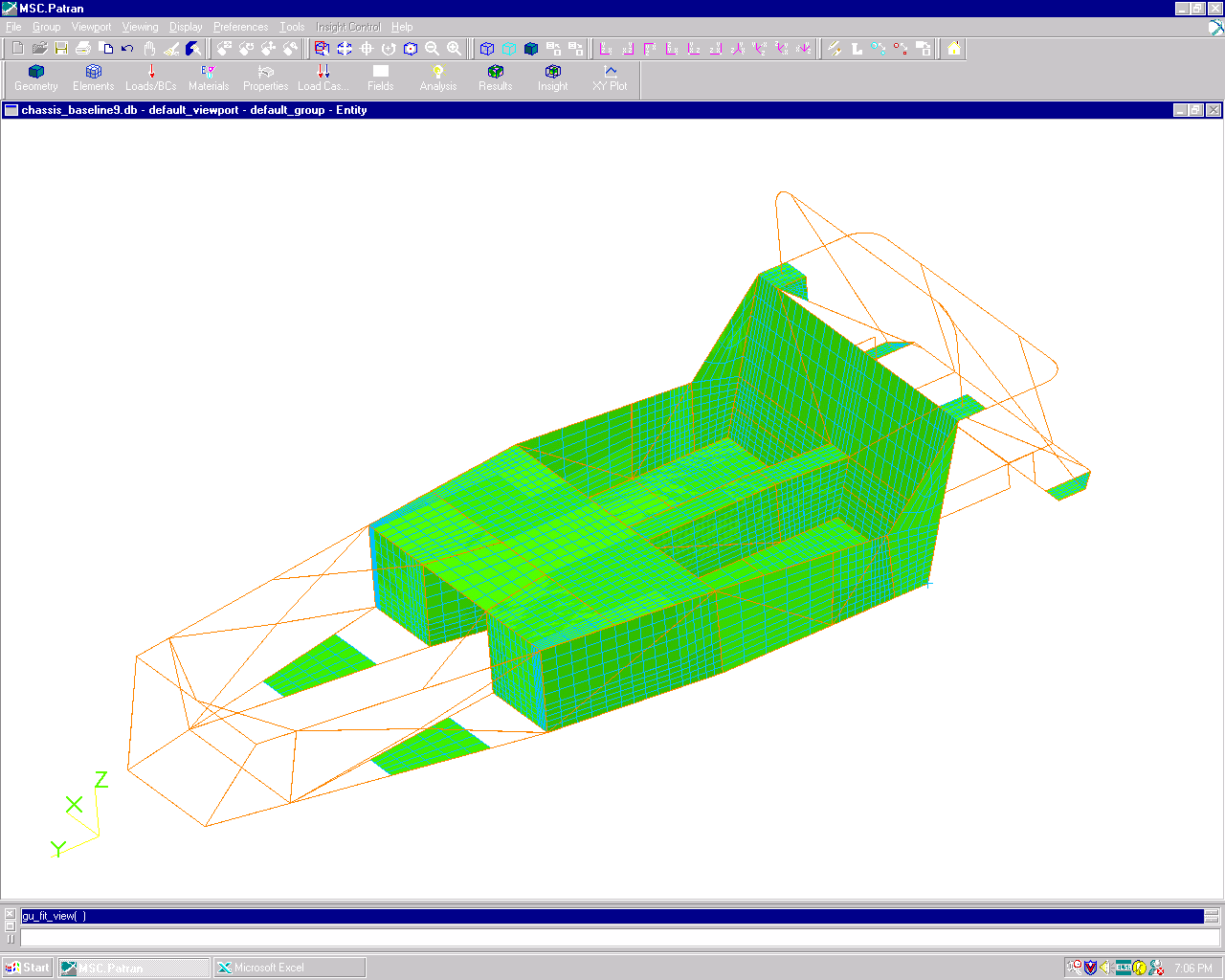
As can clearly be seen in Table 7 reducing the open section of the passenger compartment by the panelling of the dash bar area and footwell tops considerably increases the torsional stiffness of this area. This section is already relatively stiff in comparison to the open and untriangulated engine bay yet this modification sees an improvement to the torsional stiffness of over 40% on the previous model. The panelling creates a shear panel across this section, which closes part of a face of the open torsion box created by the passenger compartment. This modification is also realised in the increase in the efficiency of the chassis with a rise of 20% over the previous model and a 76% increase over the original design. The panels are mild steel of 1.6mm thickness.
8.1.7 Addition of aluminium side panels to passenger compartment

Fig. 37
Table 8

The side panels again form shear panels along the passenger compartment sides helping to further close the passenger compartment further [Fig. 37]. These panels are polished aluminium for aesthetic purposes. This proves they do however contribute to the torsional stiffness. Their contribution is small however as the efficiency of the chassis is reduced in comparison to the previous model. These panels are always fitted to the chassis’ by Luego.
8.1.8 Conversion of dash panel, transmission panels and rear wall to Aluminium

Fig. 38
Table 9

As can be seen from Table 9 changing the panels from steel of 1.6mm thickness to aluminium of the same thickness drops the stiffness quite dramatically (almost 50%). However, it does show the weight advantage of aluminium over steel as the mass is reduced by almost 20Kg. If the stiffness of the chassis can be increased without using these mild steel shear panels then the mass advantage of aluminium can be fully utilised in these areas.
