

Safety Interlocking Between High Voltage Supply Networks
100 metres below sea level, the tunnel directly linking France and England is a route used by passenger trains and shuttles at a frequency of 20 crossings per hour, of which 5 are by Eurostar high-speed-trains travelling at 160 km/hr. But it is also a "building" which requires permanently assured lighting, air conditioning, safety…
Total installed power is 400 MW, of which 140 MW is for utilities and auxiliaries! Supply of electrical power is absolutely vital and is assured jointly by the United Kingdom and France. Transmanche Link (TML), responsible for the design and construction of the project for Eurotunnel, has installed a high voltage dual distribution network incorporating a safety interlocking system with active redundancy which was engineered and produced by Telemecanique. Ten TSX series 7 programmable controllers located in 5 stations linked by fibre optics along the 50 km of tunnel guarantee continuity of service of the electricity supply.
140 MW for tunnel auxiliaries : Coquettes sub-station and control room
The tunnel
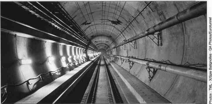
In fact "the tunnel" consists of 2 single track rail tunnels, North and South, 7.60 metres in diameter, linked every 375 metres to a central service tunnel 4.80 metres in diameter. They are also directly linked between each other every 250 metres by branch tunnels designed to relieve air compression effects caused by train movement.
The entire project, 150 km of tunnel with a volume of more than 6 million cubic metres, requires a 21 kV electrical power supply for all auxiliaries, lighting, ventilation, cooling, fire safety precautions, etc. In normal operation, this electrical supply is shared between the HV stations at Coquelles, France and Folkestone, England, which are themselves connected to the EDF (Electricite de France) and SEEBOARD (South East Electricity Board) networks respectively. A single national network can however assure supply of the total installation in the event of failure of the other. In addition, in the unlikely event of simultaneous failure of both national networks, 2 standby generating installations, one located at Puits de Sangatte and the other at Shakespeare Cliff, can each supply half of the auxiliary 21 kV network.
Well-defined HV supply network reconfiguration sequences have been developed corresponding to all possible situations and include load shedding, opening of loops, starting and coupling of standby generator sets, etc.
As the EDF and SEEBOARD networks are not in phase, any possibility of parallel operation is totally excluded.
The Objective
• The safety interlocking system must assure continuity of the 21 kV supply.
• Its function is therefore to inhibit incorrect closing commands transmitted by the control system to the circuit breakers separating the two networks.
The Solution
The 21 kV interlocking system installed corresponds to an active redundancy model. It is designed to offer maximum availability using "Fail Operational" criterion, which means that a single failure does not result in stoppage of the installation and that tolerance to failures is pushed to a maximum wherever possible. The entire network is controlled by 5 stations each comprising two TSX series 7 redundant programmable controllers linked by Uni-Telway. Each PLC receives data on the status of the circuit breakers - open, closed, racked in, racked out - and of the voltage controllers concerned with the interlocking system. In addition, each PLC receives data on the status of its own components, such as input/output boards, power supplies, etc., which enables it to carry out self-diagnostics.
• Each PLC carries out a correspondence check designed to detect anomalies between input data and output commands.
• Each station carries out a consistency check designed to validate the I/O information of its 2 PLCs and to correct malfunction or failures if necessary.
Permission Matrix
Data is transmitted to the other stations through 2 fibre optic dual networks and is centralised in a "Master" station. This station, located in Folkestone main west sub-station, comprises 2 TSX 87 PLCs. It develops a set of "permit to close" signals based on a permission matrix. The permits to close are immediately distributed within the "Master" station itself and to the other "Slave" stations, comprising TSX 47 PLCs, to update their outputs.
This means that only 2.5 seconds are needed to refresh the system data over the entire 50 km of tunnel and to authorize a new configuration.
Characteristics of the auxiliary network
• 2 x 225 kV / 21 RV and 132 kV / 21 kV 35 MVA sub-stations
• 28 x 21 kV / 3.3 kV sub-stations
• 148 x 3.3 kV / 400 V electrical rooms
• 2x6 MVA standby generator sets
• 3 pumping stations (400 to 750 kW)
• 2 x 670 mVsec ventilation and smoke extraction plants
• 4 cooling plants : 45 MW
• 2 fire safety circuits : 2 x 500 kVA
• 44 HV circuit breakers and 50 voltage controllers involved in the interlocking.
Text 4