

лекции, учебные пособия / технические тексты для группы б. / Ref 1 / Engineering today / Vario-wheel
.doc|
The vario-wheel and prospects of its application in cars Prof. Dr. Techn. Sci. N. GULIA Dipl. Eng. S. YURKOV Dipl. Eng. F. Martin, "Ikarus" plant, Budapest, Hungarian Republic Briefly about the authors of the article: N. Gulia – Prof. Dr. Techn. Sci., Moscow State Industrial University, Automobile Faculty, Machine Design Chair (Head of the Chair), Moscow, Russia. The author has more than 500 scientific works in Russian and foreign issue, 20 monographies, more than 200 inventions, including the first patent for superflywheel with a priority of 1964, and several patents for Automatic Continuously Variable Transmission (ACVT). Researches – flywheels and ACVT. He carries on scientific and practical work in association with a number of Russian and foreign corporations. Moscow State Industrial University, Russia, Moscow, 109280, Avtozavodskaja street 16, Fax: (095) 275-2256, e-mail: gulia@mail.msiu.ru (for Prof. N. Gulia). S. Yurkov – Dipl. Eng., the Principal of CVT Group, ZIL plant, Moscow, Russia. Research – ACVT. A young specialist, the author 10 scientific works, designer of ACVT for urban buses of medial and high capacity, and also for industry purposes.
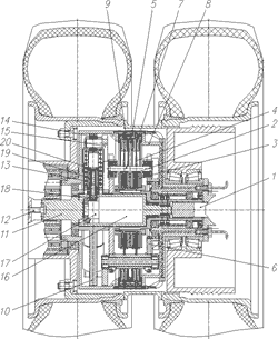
Of late mechanical continuous variable transmission based on variable-speed drives has been increasingly used in the auto industry. In the majority of cases these variable-speed drives include a flexible unit of either hauling or pushing nature. For a number of reasons they find a limited sphere of application in motor car gear box. In the authors opinion, planetary disc variable-speed drives are preferable as compared to the mentioned above thanks to higher durability, efficiency at higher gear, simplicity and small size. A detailed analysis of disc variable-speed drives and those with the flexible unit, as well as description of operational principles of the new planetary disc variable-speed drive has been carried out in a study by N. Gulia et al. [1]. Compactness, cylindrical form, indigenous automatism, as well as the possibility to carry out remote control of the mode of this automatism (control of its "rigidity") allow to build the variable-speed drive into the hub of the driving wheel jointly with board reducing gear. As a result we get a new type of a driving wheel that has been named "vario-wheel". The vario-wheel has original operational characteristics, which make it more attractive to the consumer and improve its market competitiveness. In our opinion, this, basically, refers to vehicles with several driving axles, like special tractors, including earth-moving machinery, as well as buses, motor cars and electric motor cars where electric or hydraulic hub-traction wheels application is considered to have good future. When compared, the vario-wheel and the hub-traction wheel provide the similar operational advantages – continuos change of rotational speed and torque, no need for an inter-wheel or inter-axle differential in case of continuos traction force applied to the wheels, use of independent wheel suspension when necessary. The vario-wheel needs a slightly more sophisticated system of power supply as compared to the hub-traction wheel, but its smaller size, less weight and cost, the possibility to build this device into the wheel or place it on the chassis (generator or pump, transformers, board control system), as well as its significantly higher efficiency add up to the obvious advantages. Supply of rotation to the vario-wheel under low momentum, lower than that of the engine without a gear box, requires no more additional space than in case of power supply by means of wires or liquid in tubes. It is possible to carry out power supply by means of flexible shafts in tubing that look very much the same as cables or flexible tubes. Being experts in bus production and not in multi-axle vehicles, special transport equipment or motor cars, we will accentuate prospects of the vario-wheel application in city buses production and other types of vehicles. Vario-wheels application in cars, tractors and trucks with large wheels (bulldozers, scrapers, lorries) promises good prospects and provides extremely good advantages. The torque, transmitted by the variable-speed drive, is defined by its diameter raised to the third power. Therefore, in the case of large wheels it is possible to use single-disc variable-speed drives without additional board reducing gear. The power transmitted by the disc variable-speed drives can reach 500 kWt and more for a single unit. A vario-wheel with pair diskless wheels for 12.00-20 tire (typical to city buses similar to the "Ikarus") is presented on fig. 1.
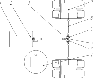
Fig. 1. The vario-wheel (figures in the AutoCAD format, 235 kb) (1) – carrier; (2) – semi-axle; (3) – Belleville spring; (4) – central friction discs; (5) – interval cone discs; (6) – case; (7) – external friction discs; (8) – axle of interval cone discs; (9) – disc spring; (10) – roller; (11) – turning lever; (12) – nut of the control system; (13) – screw of the control system; (14) – spring; (15) – cone transmission; (16) – screw; (17) – semi-coupling; (18) – reducing gear; (19) – servomotor; (20) – slotted disc. A low momentum semi-axle (2), i.e. calculated for a nominal torque which is approximately half the torque of the engine, rotates the central friction discs (4), squeezed together by a set of Belleville springs (3). The cone discs (5) joined to the carrier (1) via their axle (8) at the same time are in contact with the immobile external friction discs (7), set in a case (6) and squeezed by flat disc springs (9). (The design of the variable-speed drive is covered by a patent of the Russian Federation #2140028 of 26.05.98. by Mr. N.V. Gulia). The torque from carrier (1) is supplied to the slotted disc (20) – the output unit of the variable-speed drive – of the regular board planetary reducing gear through a system of automatic control with forced setting of modes. The half-coupling (17) can be dropped out of gear with a screw (16). The automatic control system of the variable-speed drive, covered by patent # 2138710 of 16.06.98. (by Mr. N.V. Gulia), is based on the balance of forces, acting from the side of slots in the slotted disc (20) and springs (14) squeezing rollers (10), the axles of which are connected to the turning lever (11), moving the axle (8) of the interval discs radial-wise and changing the transmitting ratio of the variable-speed drive. The automatic regulating mode depends on the compression of the springs (14), carried out by a servomotor (19), in our case of D-400V type, 400 Wt power at 8000 RPM (24 V) with a planetary or wave reducing gear (18) with transmitting ratio 150 and cone transmission (15), allowing the screws (13) of the controlling system to move inside the nut (12). It should be mentioned that this system provides for a forced regulation of the transmitting ratio of the variable-speed drive as well, efficient at low (creeping) speed of the vehicle. In the extreme (upper) position of the discs (5) the transmitting ratio of the variable-speed drive is 9.91, in the central (low) position – 1.27. The decreasing transmitting ratio of the board reducing gear is 3.7, thus the overall transmitting ratio of the mechanism of the vario-wheel is between 36.7 and 4.7. Assuming that the rotational speed of the semi-axle at starting-off is 800 RPM, the vario-wheel at maximum transmitting ratio will be rotating at about 20 RPM (taking into account the imminent slipping during transmission) and the speed of the bus will be about 1 m/sec or 3.6 km/h. This corresponds to the actual bus starting-off conditions. When the semi-axle rotates at 2000 RPM and the gear ratio is lowest, the speed of the bus is about 22 m/sec or 76 km/h, which is quite sufficient for an urban transport. The expected efficiency of the variable-speed drive at starting-off is about 0.8, at maximum speed – 0.96. This value is ensured by the planetary design of the variable-speed drive and the genuine efficiency of the variable-speed drive friction contacts, with initial momentum of 600 Nm. The maximum traction effort on the wheel can reach 3.5...40 kN, which means clutch limit with the driving axle loading of 9 t. Such a traction performance is acceptable for heavy trucks and vehicles with enhanced cross-country characteristics and by far exceeds the requirements for buses. It should be emphasized that the contact tensions in the variable-speed drive reach only half of the acceptable level, leaving a resource for an 8-fold increase of the transmitted momentum or the possibility to cut by half the diameter of the variable-speed drive which is provided by the point starting contact of the transmission, but the variable-speed drive efficiency drops slightly. The system of control can provide for a forced regulation of the transmitting ratio at speeds up to 10 km/h with high accuracy of speed retention (during maneuvering in parking lots, etc.) and automatic adjustment of transmitting ratios of the left and right vario-wheels depending on the turning angle of the regulated wheel. During regular movement of the bus only the mode of automatic control is adjusted: when the spring (14) is squeezed hard, the mode is "rigid", i.e. the transmitting ratio of the variable-speed drive rises slowly following the increase of road resistance; when the spring (14) is squeezed with less strength, the mode is "progressive", i.e. the transmitting ratio of the variable-speed drive and the related speed of the vehicle change progressively with the increase of road resistance. In these cases turning of the vehicle does not require inter-wheel differentials in transmission, because the insignificant change of rotational speed in any mode will just slightly change the traction effort on the wheels, which should hardly have any effect on the kinematics or dynamics of the turn. In case of wheels slipping (i.e., on the ice-crusted ground), this property should be, as well as in case of the soft ground for cross-country vehicles, substituting for the increased friction differential. Contrary to the majority of automatic transmissions, our structure provides a large range of movement mode regulation. The servomotor is put into operation only to change the mode of movement, i.e. only occasionally. Similar to hub-traction wheels the vario-wheels can be used for ordinary engine driven power units, as well as for hybrid systems that include power accumulators. From our point of view, in hybrid systems, which use heat engines, as well as heat elements for main sources of energy, it is viable to use accumulators of mechanical energy – super-flywheels. In case of heat engines, producing energy in the form of rotation of the shaft, used for rotation of the semi-axle of the driving wheel, the viability of using an accumulator where energy is stored in the form of rotation of the super flywheel is only obvious. For cases of use of heat elements in electric motor cars as well as electric buses this viability has been proved in publications [2] and [3]. Use of the vario-wheel within the mentioned concept is equivalent to use of the variable-speed drive in transmission, the former, however, being preferable for the electric bus due to assembly requirements. The scheme of the most used hybrid power unit for a car (bus) with the vario-wheel is shown on fig. 2. The engine (1) with the clutch (2) rotates the pinion (3) of the main gear as well as the super-flywheel (9) through the corresponding gear with the coupling of the clutch. The main gear can go into reverse by means of a coupling with teeth or cam (7), connecting semi-axle wheels of the front (8) or rear (6) drive to the semi-axle (5), which transmits the rotational momentum to the vario-wheels (4). When the coupling (7) is in the middle position the neutral is activated.
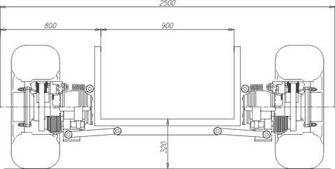
Fig. 2. Diagram of a hybrid power unit of a car (bus) with vario-wheels (figures in the AutoCAD format, 235 kb) (1) – engine; (2) – clutch; (3) – pinion of the main gear; (4) – vario-wheel; (5) – semi axle; (6) – semi-axle gear-wheel of the rear drive; (7) – coupling; (8) – semi-axle gear-wheel of the front drive; (9) – super-flywheel It has already been mentioned that the transmitting ratio of the main gear is close to 1, therefore neither its sizes should be big nor the momentum on it should be high. In particular, the momentum being transmitted by the semi-axle is half the figure of that on the original shaft of the transmission after clutching. As comparison, it can be mentioned that the sizes of cone wheels (3), (6) and (8) are close to those of the pinion of the driving gear in cars, designed for close torque proximity. Wheel bearings will have similar size, so the space occupied by the main reversing gear by height can freely fit into the thickness of the bus floor, i.e. the height of the load-bearing elements. This article does not deal with the operating principle of the hybrid car power unit. The subject has been covered earlier, specifically, in [4] that provided a detailed analysis. We should remark that in order to convert the hybrid system into an ordinary one it is necessary to remove the super-flywheel accumulator and the corresponding drive. The engine power increases twofold compared with the hybrid. When transforming the scheme on the fig. 2 into a system of an electric motor car, the engine with the clutch should be removed and a built-in accelerating electric engine should be supplied with any electric power source, with heat elements, in particular [2, 3]. Vario-wheels application has a number of configuration advantages compared with hub-traction wheels. Let us take the example of a most used bus assembly with a low floor level – only 320 mm, with hub-traction wheels and independent ZF suspension – fig. 3. The design with hub traction provides a gangway only 900 mm wide. Note, that usually large dimensional generator and frequency transformers (or inverters) should always be present in this system.
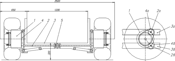
Fig. 3. Assembly of a low-floor bus with hub-traction wheels and independent suspension (figures in the AutoCAD format, 235 kb) The system with the vario-wheel (fig. 4) due to small axle dimensions, not exceeding the axle dimensions of the wheel, with the same floor height requirement, provides for a gangway approximately 300 mm wider. Traction engines of the hub-traction wheel, a generator, transformers are eliminated. The drive efficiency is increased as well as the changing range of the torque, which is extremely important in hybrid systems, where the energy passes through the drive twice – from the accumulator to the wheels and back during energy recuperation. The maximum torque that is transferred by the variable-speed drive by far exceeds that of the traction engine with similar dimensions and, therefore, ultimately ensures high traction and dynamics of the vehicle. Supply of rotation to the vario-wheel (1) can be carried out in the case of an independent suspension independently of the floor level or adjustment of its height (which, by the way, is very limited in buses with pneumatically regulated suspension). This can be achieved by fixing the main gear (5) and the semi-axle (3) in the floor of the vehicle (4) and connecting them with the input shaft of the vario-wheel by means of a rolling cylindrical reducing gear (2), as shown in the right corner of fig. 4. The floor can be adjusted to different levels in relation to the surface of the road – (3a) and (3b) respectively, transmitting rotation of the semi-axle to the input of the vario-wheel. Revolving of the cylindrical wheels of the rolling reducing gear, which theoretically changes the transmitting ratio from the main gear to the rim of the wheel, practically does not influence (just as the turning of the vehicle) the momentum, transmitted by the vario-wheel due to the "progressive" characteristic of the variable-speed drive. For cross-country vehicles this principle scheme can be "turned round" by 180 degrees and the low clearance that is acceptable to buses, can be changed to a higher figure, which is required for good cross-country performance.
Fig. 4. Assembly of a bus with vario-wheels and independent suspension (figures in the AutoCAD format, 235 kb) (1) – vario – wheel; (2) – rolling cylindrical reducing gear; (3) – semi-axle; (4) – bus floor level; (5) – main gear; (a) and (b) respectively upper and lower bus floor level Due to the ease with which high transmitting figures can be achieved (by a board reducing gear, variable-speed drive, rolling reducing gear) application of vario-wheels allows to use small sized high speed engines without the risk of increasing the transmitting ratio and radial dimensions of the main gear. It also keeps the transmitting figure close to 1 and retains the minimal radial dimensions of the high speed low momentum main reversing gear, that is recommended to be carried out by a cone or round tooth. It can be considered to have good prospects to change the clutch of the engine by a high-momentum synchronizer and place the clutch with pneumatic control system directly into the vario-wheel, in the free space between the board reducing gear and the rim of the wheel. This should raise the ultimate resource of transmission, because its loading will be happening after the oil wedge has been already built-up. This refers to vario-wheels used in motor cars, buses, as well as powerful transport vehicles mentioned above. Should it be impossible for some reason to place the variable-speed drive in the propeller, then this type of a variable-speed drive can be used with equal success as a small-sized automatic gear-box for all types of aforementioned vehicles.
References:
|
|
Date of the publication: January 23, 2001 |